HIKVISION DS-2CE10DF3T-F User Manual Download Page 6


Ceiling mounting and wall mounting are similar. 

Following steps take ceiling mounting as an example. 
Steps: 
1.


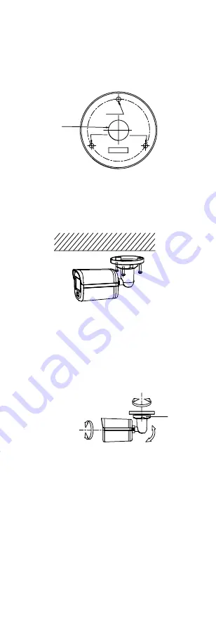
Paste the drill template (supplied) to the place 
where you want to install the camera. 

2.


(Optional) For cement ceiling, drill the screw holes 
with a 5.5 mm drill and insert the supplied wall 

plugs. 

Screw


Hole

Screw


Hole

Screw


Hole

templat e

Cable 

Hole


Figure 2-1


Drill Template 

3.


(Optional) Drill the cable hole, when the cables are 
routed through the ceiling. 

4.


Align the screw holes in the bracket to the ceiling, 

and secure the camera with three PA4 × 25 screws 
(supplied). 


Figure 2-2


Secure the Camera to the Ceiling 

5.


Connect the power cord and video cable. 

6.


Power on the camera to check whether the image 
on the monitor is gotten from the optimum angle. If 
not, turn the trim ring counterclockwise to loosen it 

and adjust the positions according to the figure 
below. 

Rotation Position 

[0° to 360°]

Tilt Position 

[0° to 90°]

Pan Position 

[0° to 360°]

Trim Ring


Figure 2-3


3-Axis Adjustment 

7.


Turn the trim ring clockwise to lock the positions. 

2.1.2


Ceiling/Wall Mounting with Junction Box 

Before you start: 


You need to purchase a junction box in advance. 


Ceiling mounting and wall mounting are similar. 

Following steps take wall mounting as an example. 

Steps: 
1.


Paste the drill template for junction box to the place 

where you want to install the camera. 

2.


(Optional) For cement wall, drill the screw holes 
with a 5.5 mm drill and insert the supplied wall 

plugs. 

Summary of Contents for DS-2CE10DF3T-F

Page 1: ...2CE10DF3T PF Type II Camera DS 2CE12DF8T F DS 2CE12DF3T F Type III Camera DS 2CE70DF8T PF DS 2CE70DF3T PF Type IV Camera DS 2CE70DF8T MF DS 2CE70DF3T MF Type V Camera DS 2CE72DF8T F DS 2CE72DF3T F Th...

Page 2: ...eration EU Conformity Statement This product and if applicable the supplied accessories too are marked with CE and comply therefore with the applicable harmonized European standards listed under the L...

Page 3: ...evice is firmly fixed if wall mounting or ceiling mounting is adopted If smoke odor or noise rise from the device turn off the power at once and unplug the power cord and then contact the service cent...

Page 4: ...ight 3 axis adjustment 1 2 Overview 1 2 1 Overview of Type I Camera Power Cord Video Cable Switch Button Bracket Main Body Lens Figure 1 1 Overview of Type I Camera Note Press and hold the switch butt...

Page 5: ...witch button for 5 seconds to switch the video output Four kinds of video outputs are available TVI AHD CVI and CVBS 2 Installation Before you start Make sure that the device in the package is in good...

Page 6: ...ect the power cord and video cable 6 Power on the camera to check whether the image on the monitor is gotten from the optimum angle If not turn the trim ring counterclockwise to loosen it and adjust t...

Page 7: ...n box body on the wall with three PA4 25 screws supplied Figure 2 6 Secure the Junction Box on the Wall 7 Route the cables through the bottom cable hole or side cable hole of the junction box and conn...

Page 8: ...camera with three PA4 25 screws supplied Figure 2 9 Secure the Camera to the Ceiling 5 Connect the power cord and video cable 6 Power on the camera to check whether the image on the monitor is gotten...

Page 9: ...ra onto the gang box Figure 2 13 Fit the Camera onto the Gang Box 5 Turn the camera clockwise until it snaps into the gang box Figure 2 14 Snap the Camera into the Gang Box 6 Connect the power cord an...

Page 10: ...routed through the ceiling 5 Secure the junction box body on the ceiling with three PA4 25 screws that come with the junction box Figure 2 17 Secure the Junction Box Body 6 Route the cables through t...

Page 11: ...x the Wall Mount 3 Use PM4 10 screws to fix the gang box onto the wall mount Figure 2 21 Fix the Gang Box 4 Repeat the step 4 to 6 of 2 4 1 Ceiling Mounting Without Junction Box to finish the installa...

Page 12: ...to the Ceiling 6 Align the screw hole with the triangle mark to install the camera back to the base and secure it Triangle Mark Figure 2 26 Install the Camera Back 7 Connect the power cord and video c...

Page 13: ...e apart the junction box 2 Paste the drill template for junction box to the place where you want to install the camera 3 Optional For cement ceiling drill the screw holes with a 5 5 mm drill and inser...

Page 14: ...g Mounting Without Junction Box to finish the installation Figure 2 33 Finish the Installation 2 4 3 Wall Mounting Before you start You need to purchase a wall mount in advance Steps 1 Drill 10 mm scr...

Page 15: ...Installation of Type V Camera 2 5 1 Ceiling Mounting without Junction Box Steps 1 Paste the drill template supplied to the place where you want to install the camera 2 Optional For cement ceiling dri...

Page 16: ...pan position 0 to 360 2 Move the main body up and down to adjust the tilt position 0 to 75 3 Rotate the main body to adjust the rotation position 0 to 360 2 5 2 Ceiling Mounting with Junction Box Incl...

Page 17: ...he camera onto the gang box Figure 2 45 Fit the Camera 7 Turn the camera clockwise until it snaps into the gang box Figure 2 46 Snap the Camera into the Gang Box 8 Secure the junction box body on the...

Page 18: ...xpansion bolts to fix the wall mount onto the wall Figure 2 49 Fix the Wall Mount 3 Use three PM4 10 screws to fix the gang box onto the wall mount Figure 2 50 Fix the Gang Box 4 Repeat the step 4 to...

Page 19: ...n or calling preset No 95 EXPOSURE EXPOSURE MODE MAIN MENU VIDEO SETTINGS FUNCTIONS EXIT SAVE EXIT AGC BACK EXIT CONTRAST SHARPNESS SATURATION 3DNR MIRROR BACK BACK EXIT VIDEO FORMAT FACTORY DEFAULT S...

Page 20: ...the camera provide clear images even under back light circumstances When there are both very bright and very dark areas simultaneously in the field of view WDR balances the brightness level of the who...

Page 21: ...mination MANUAL You can set the R GAIN B GAIN value to adjust the shades of red blue color of the image WHITE BALANCE MODE R GAIN B GAIN BACK EXIT SAVE EXIT MANUAL 5 5 Figure 3 4 WHITE BALANCE BRIGHTN...

Page 22: ...upplement light to FLASHING or SOLID under ALARM MODE Note The lighting function of the supplement light takes priority over the alarm function The alarm mode settings only take effect when the supple...

Reviews: