HIKVISION D7T Series User Manual Download Page 10


ATW 

In 

ATW

 mode, white balance is being adjusted 

automatically according to the color temperature of the 

scene illumination. 

MWB 

You can set the 

R GAIN

/

B GAIN

 value from 0 to 255 to 

adjust the shades of red/blue color of the image. 
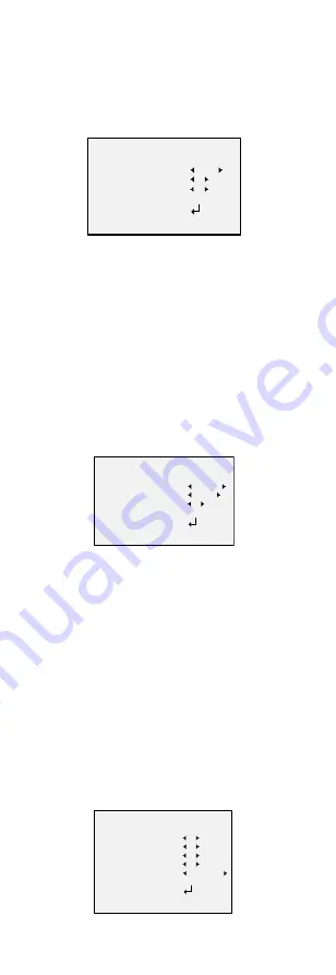
WB

 MODE                  
      R GAIN         
      B GAIN                    
                      
 RETURN           

MWB

5

5


Figure 3-3


MWB Mode 

3.2.4


DAY-NIGHT 

Color

B/W

, and 

SMART

 are selectable for DAY and 

NIGHT switches. 

COLOR 

The image is colored in day mode all the time.   

B/W 

The image is black and white all the time, and the IR 
LED turns on in the low-light conditions. 

SMART 

You can select to turn on/off the 

INFRARED

 and set the 

value of SMART IR in this menu. 

DAY/NIGHT

 MODE                  
      INFRARED         
      SMART IR                    
                      
 RETURN           

SMART

OPEN

1


Figure 3-4


  Day & Night 


INFRARED 

You can select to turn on/off the IR LED to response to 
the requirements of different circumstances. 


SMART IR 

The 

Smart IR

 function is used to adjust the light to its 

most suitable intensity, and to prevent the image from 
over exposure. The 

SMART IR

 value can be adjusted 

from 0 to 3. The higher the value is, the more obvious 

effects are, and it is disabled when the value is 0. 

3.2.5


VIDEO SETTING 

Move the cursor to 

VIDEO SETTING

 and press the 

confirm button to enter the submenu. 

CONTRAST

SHARPNESS

COLOR GAIN

DNR

 and 

MIRROR

 are 

adjustable. 

VIDEO SET TING

CONTRAST
SHARPNESS                  
COLOR GAIN         
DNR
MIRROR                    
                      
RETURN           

5

5

5

5

DEFAULT


Figure 3-5


  Video Setting 

Summary of Contents for D7T Series

Page 1: ...models below Type Model Type I Camera DS 2CE16D F 7T IT Type II Camera DS 2CE16D F 7T IT1 DS 2CE16D F 7T IT3 DS 2CE16D F 7T IT5 This manual may contain several technical incorrect places or printing errors and the content is subject to change without notice The updates will be added to the new version of this manual We will readily improve or update the products or procedures described in the manu...

Page 2: ...rference 2 This device must accept any interference received including interference that may cause undesired operation EU Conformity Statement This product and if applicable the supplied accessories too are marked with CE and comply therefore with the applicable harmonized European standards listed under the Low Voltage Directive 2006 95 EC the EMC Directive 2004 108 EC 2002 96 EC WEEE directive P...

Page 3: ...t filter with auto switch OSD menu parameters are configurable Auto white balance and internal synchronization SMART IR mode True WDR Advanced 3 axis design meets different installation requirements 1 2 Overview This manual applies to two types of bullet cameras The overviews of each type are shown in the figures below please refer to the actual sample 1 2 1 Overview of Type I Camera Main Body Pho...

Page 4: ... not function properly please contact your dealer or the nearest service center Do not disassemble the camera for repair or maintenance by yourself 2 1 Installation of Type I Camera Both wall mounting and ceiling mounting are suitable for the bullet camera Ceiling mounting will be taken as an example in this section You can take steps of ceiling mounting as a reference if wall mounting is adopted ...

Page 5: ... 360 Rotation Position Range 0 360 Figure 2 3 3 axis Adjustment 6 Tighten the fixing screws and the trim ring to fix the camera 2 1 2 Ceiling Wall Mounting with Gang Box You need to purchase a gang box separately if you adopt celling mounting Steps 1 Take apart the gang box and align the screw holes of the bullet camera and the gang box cover 2 Route the cables through the cable hole of gang box a...

Page 6: ...gle 2 2 Installation of Type II Camera 2 2 1 Ceiling Wall Mounting without Gang Box Steps 1 Attach the drill template supplied to the place where you want to fix the camera and then drill the screw holes and the cable hole in the ceiling wall according to the drill template Figure 2 7 Drill Template 2 Route the cables through the cable hole 3 Secure the camera to the ceiling with the supplied Scre...

Page 7: ...screw after completing the adjustment P Screw T Screw R Screw Tilt Position Range 0 180 Pan Position Range 0 360 Rotation Position Range 0 360 Figure 2 9 3 axis Adjustment 2 2 2 Ceiling Wall Mounting with Gang Box You need to purchase a gang box separately if you adopt celling mounting Steps 1 Take apart the gang box and align the screw holes of the bullet camera and the gang box cover Figure 2 10...

Page 8: ... to step 5 of 2 2 1 to adjust the camera to get an optimum angle 3 Menu Description MAIN MENU AE WB DAY NIGHT VIDEO SETTING RESET SAVE EXIT BRIGHTNESS EXPOSURE MODE GAIN ATW MWB COLOR B W CONTRAST SHARPNESS COLOR GAIN DNR MIRROR SMART FORMAT SETUP Figure 3 1 Main Menu Overview With a camera controller purchased separately or calling the preset No 95 of DVR you can select the menu and adjust the pa...

Page 9: ... processing or other conditions of under exposure to get an optimum image BLC Backlight Compensation BLC Backlight Compensation compensate light to the object in the front to make it clear but this causes the over exposure of the background where the light is strong When BLC is selected as the exposure mode the BLC level can be adjusted from 0 to 8 WDR Wide Dynamic Range The wide dynamic range WDR...

Page 10: ...and set the value of SMART IR in this menu DAY NIGHT MODE INFRARED SMART IR RETURN SMART OPEN 1 Figure 3 4 Day Night INFRARED You can select to turn on off the IR LED to response to the requirements of different circumstances SMART IR The Smart IR function is used to adjust the light to its most suitable intensity and to prevent the image from over exposure The SMART IR value can be adjusted from ...

Page 11: ...image flips 180 degrees both horizontally and vertically 3 2 6 RESET Reset all the settings to the default 3 2 7 SAVE EXIT Move the cursor to SAVE EXIT and press OK to save the setting and exit the menu 4 IR Reflection Prevention For the camera that supports IR you are required to pay attention to the following precautions to prevent IR reflection Dust or grease on the dome cover will cause IR ref...

Reviews: