HIKVISION D0T User Manual Download Page 12


3


Menu Description 

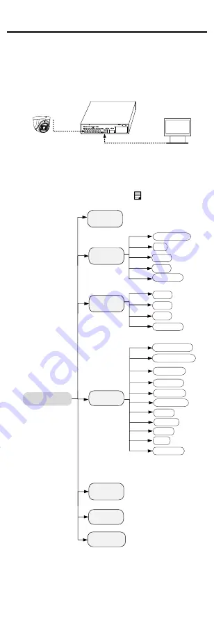
Please follow the steps below to call the menu. 

Note: 

The actual display may vary with your camera model. 
Steps: 
1.


Connect the camera with the TVI DVR, and the 

monitor, shown as the figure 3-1. 

Camera

TVI DVR

Monitor


Figure 3-1


Connection 

2.


Power on the camera, TVI DVR, and the monitor to 
view the image on the monitor. 

3.


Click PTZ Control to enter the PTZ Control interface. 

4.


Call the camera menu by clicking      button, or call 
the preset No. 95. 

EXPOSURE

EXPOSURE MODE

MAIN MENU

VIDEO 

SETTINGS

EXIT 

SAVE & EXIT

AGC

BACK

EXIT

CONTRAST

SHARPNESS

SATURATION

DNR

MIRROR

BACK

VIDEO 

FORMAT

FACTORY 

DEFAULT

SAVE & EXIT

WHITE BALANCE

BRIGHTNESS

EXIT

SAVE & EXIT 

IMAGE MODE

DAY/NEIGHT

MODE

BACK

EXIT

SAVE & EXIT


Figure 3-2


Main Menu Overview 


Summary of Contents for D0T

Page 1: ...Camera DS 2CE56D0T IR F DS 2CE56D0T IRP F Type III Camera DS 2CE56D0T IT1 3 F Type IV Camera DS 2CE76D0T ITPFS Type V Camera DS 2CE76D0T ITMFS Type VI Camera DS 2CE56D0T IRMM F This manual may contai...

Page 2: ...eration EU Conformity Statement This product and if applicable the supplied accessories too are marked with CE and comply therefore with the applicable harmonized European standards listed under the L...

Page 3: ...mounting is adopted If smoke odor or noise rise from the device turn off the power at once and unplug the power cord and then contact the service center Never attempt to disassemble the camera by unpr...

Page 4: ...efer to 4 in 1 video output cameras 1 2 1 Overview of Type I Camera Mounting Base Clip Plate Main Body Enclosure Video Cable Power Cord Figure 1 1 Overview of Type I Camera without F Note This camera...

Page 5: ...II Camera without F Note This camera is TVI only DC12V IN Enclosure Main Body Switch Button Power Cord Video Cable Mounting Base Figure 1 6 Overview of Type III Camera with F Note Press and hold the s...

Page 6: ...able TVI AHD CVI and CVBS 1 2 6 Overview of Type VI Camera Black Liner Bubble Adjusting Screws IR Zoom Camera Module Power Cord Video Cable Figure 1 9 Overview of Type VI Camera without F Note This ca...

Page 7: ...act your dealer or the nearest service center Do NOT disassemble the camera for repair or maintenance by yourself 2 1 Installation of Type I V Camera Before you start The installation of ceiling mount...

Page 8: ...figure below to get an optimum angle Pan Position 0 to 360 Rotation Position 0 to 360 Tilt Position 0 to75 Figure 2 4 3 Axis Adjustment 2 2 Installation of Type II Camera Before you start The install...

Page 9: ...Position 0 to75 Figure 2 7 3 Aixs Adjustment 8 Tighten the trim ring by clockwise rotating it 2 3 Installation of Type III IV Camera Before you start The installation of ceiling mounting and wall moun...

Page 10: ...2 4 Installation of Type VI Camera Before you start The installation of ceiling mounting and wall mounting are similar Following takes ceiling mounting as an example 1 Drill the screw holes and cable...

Page 11: ...Rotation Position 0 to 350 Tilt Position 0 to70 Pan Position 0 to 350 Figure 2 14 3 Aixs Adjustment 7 Install the black liner and the bubble back Figure 2 15 Install the Black Liner and the Bubble...

Page 12: ...camera TVI DVR and the monitor to view the image on the monitor 3 Click PTZ Control to enter the PTZ Control interface 4 Call the camera menu by clicking button or call the preset No 95 EXPOSURE EXPO...

Page 13: ...t this may cause the over exposure of the background where the light is strong HLC Highlight Compensation HLC stands for highlight compensation The camera detects the strong spots the over exposure po...

Page 14: ...on off the IR LIGHT to meet the requirements of different circumstances SMART IR The Smart IR function is used to adjust the light to its most suitable intensity and prevent the image from over expos...

Page 15: ...set the R GAIN B GAIN value to adjust the shades of red blue color of the image WHITE BALANCE MODE R GAIN B GAIN BACK EXIT SAVE EXIT MANUAL 5 5 Figure 3 6 MWB MODE BRIGHTNESS Brightness refers to the...

Page 16: ...ertically 3 5 FACTORY DEFAULT Reset all the settings to the factory default 3 6 EXIT Move the cursor to EXIT and click Iris to exit the menu 3 7 SAVE EXIT Move the cursor to SAVE EXIT and click Iris t...

Reviews: