HIKOKI G 1813DF Handling Instructions Manual Download Page 10

10

e) Support panels or any oversized workpiece to 

minimize the risk of wheel pinching and kickback.

  Large workpieces tend to sag under their own weight. 

Supports must be placed under the workpiece near the 

line of cut and near the edge of the workpiece on both 

sides of the wheel.

f)  Use extra caution making a “pocket cut” into 

existing walls or other blind areas.

  The protruding wheel may cut gas or water pipes, 

electrical wiring or objects that can cause kickback.

g)  Do not attempt to do curved cutting.

  Overstressing the wheel increases the loading and 

susceptibility to twisting or binding of the wheel in the cut 

and the possibility of kickback or wheel breakage, which 

can lead to serious injury.

GENERAL SAFETY INSTRUCTIONS 

FOR CORDLESS DISC GRINDERS

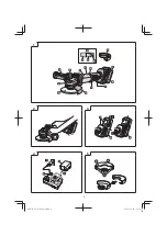
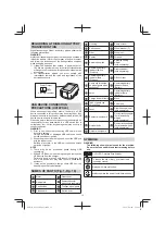
–  Attach the side handle 

fi

 rmly, hold the housing and the 

side handle with both hands, and support the tool body 

securely. (

Fig. 2

)

–  Check that speed marked on the wheel is equal to or 

greater than the rated speed of the grinder;

–  Ensure that the wheel dimensions are compatible with 

the grinder;

–  Inspect the grinding wheel before use, do not use 

chipped, cracked or otherwise defective products;

–  Ensure that mounted wheels and points are 

fi

 tted  in 

accordance with the manufacturer’s instructions;

–  Ensure that blotters are used when they are provided 

with the bonded abrasive product and when they are 

required;

–  Ensure that the abrasive product is correctly mounted 

and tightened before use and run the tool at no-load for 

30 seconds in a safe position, stop immediately if there 

is considerable vibration or if other defects are detected. 

If this condition occurs, check the machine to determine 

the cause;

–  If a guard is equipped with the tool never use the tool 

without such a guard;

–  Do not use separate reducing bushings or adapters to 

adapt large hole abrasive wheels;

–  For tools intended to be 

fi

 tted with threaded hole wheel, 

ensure that the thread in the wheel is long enough to 

accept the spindle length;

–  Do not use cutting o

  wheel for side grinding;

–  Ensure that sparks resulting from use do not create 

a hazard e.g. do not hit persons, or ignite 

fl

 ammable 

substances;

–  Ensure that ventilation openings are kept clear when 

working in dusty conditions, if it should become 

necessary to clear dust, 

fi

 rst disconnect the tool from 

the mains supply (use non metallic objects) and avoid 

damaging internal parts;

–  Always use eye and ear protection. Other personal 

protective equipment such as dust mask, gloves, helmet 

and apron should be worn;

–  Pay attention to the wheel that continues to rotate after 

the tool is switched o

 .

–  When using dual-purpose (combined grinding and 

cut-o

  wheels), use only the type A wheel guard. (See 

page 18)

–  When using a type A wheel guard for lateral grinding, 

the guard may interfere with the workpiece causing poor 

control.

–  When using a type B wheel guard for cutting-o


operations with bonded cut-o

  wheels, there is an 

increased risk of exposure to emitted sparks and 

particles, as well as exposure to wheel fragments in the 

event of a wheel burst.

–  When using a type A, B wheel guard for cutting-o


operations or lateral grinding in concrete or masonry, 

there is an increased risk of exposure to dust and loss of 

control resulting in kickback.

–  Do not use any segmented diamond cut-o

  wheels with 

segment slits >10 mm. Only negative segment cutting 

angles are permitted.

–  The workpiece must lay 

fl

 at and be secured against 

slipping, e.g. using clamps. Large workpieces must be 

su

  ciently supported.

–  Observe the speci

fi

 cations of the tool or accessory 

manufacturer. Protect wheels from grease or impact.

–  Accessories must be stored and handled with care in 

accordance with the manufacturer's instructions.

WARNING

–  When using a cutting-o

  wheel, be sure to attach a type  

A wheel guard.

–  When using a grinding wheel, be sure to attach a type B 

wheel guard.

–  For safety reasons, only use the wheel guard provided 

for the respective accessory. Using an incorrect wheel 

guard can lead to loss of control and serious injuries. 

See also page 18.

ADDITIONAL SAFETY WARNINGS

1.  Ensure that the depressed center wheel to be utilized is 

the correct type and free of cracks or surface defects. 

Also ensure that the depressed center wheel is properly 

mounted and the wheel nut is securely tightened.

2. Con

fi

 rm that the push button is disengaged by pushing 

push button two or three times before switching the 

power tool on.

3.  To prolong the life of the machine and ensure a 

fi

 rst 

class 

fi

 nish, it is important that the machine should not 

be overloaded by applying too much pressure. In most 

applications, the weight of the machine alone is su

  cient 

for e

 ective grinding. Too much pressure will result in 

reduced rotational speed, inferior surface 

fi

 nish,  and 

overloading which could reduce the life of the machine.

4.  The wheel continues to rotate after the tool is switched 

o

 .


After switching o

  the machine, do not put it down until 

the depressed center wheel has come to a complete 

stop. Apart from avoiding serious accidents, this 

precaution will reduce the amount of dust and swarf 

sucked into the machine.

5.  When the machine is not use, the power source should 

be disconnected.

6.  Be sure to switch OFF and pull out the battery to avoid 

a serious accident before the depressed center wheel is 

assembling and disassembling.

7.  Be careful of brake kickback.


This cordless disc grinder features an electric brake that 

functions when the switch is released. As there is some 

kickback when the brake functions, be sure to hold the 

main body securely.

8.  If you notice that the unit is  generating unusually high 

temperatures, operating poorly, or making abnormal 

noises, immediately stop using and shut o

  the power 

switch. Request an inspection and repair from the dealer 

where you purchased the unit or a HiKOKI Authorized 

Service Center.

  Continuing to use while operating abnormally might 

cause injuries.

9.  If the unit is mistakenly dropped or strikes another object, 

make a thorough check of the unit for cracks, breakage 

or deformation, etc.

  Injuries might occur if the unit has cracks, breakage or 

deformation.

00Book̲G1813DF̲Aust.indb   10

00Book̲G1813DF̲Aust.indb   10

2022/08/26   15:16:39

2022/08/26   15:16:39

Summary of Contents for G 1813DF

Page 1: ...G 1813DF Handling instructions 00Book G1813DF Aust indb 1 00Book G1813DF Aust indb 1 2022 08 26 15 16 33 2022 08 26 15 16 33 ...

Page 2: ...2 1 2 3 4 5 00Book G1813DF Aust indb 2 00Book G1813DF Aust indb 2 2022 08 26 15 16 34 2022 08 26 15 16 34 ...

Page 3: ...3 6 7 00Book G1813DF Aust indb 3 00Book G1813DF Aust indb 3 2022 08 26 15 16 36 2022 08 26 15 16 36 ...

Page 4: ...4 8 9 10 11 12 13 15 30 a b 00Book G1813DF Aust indb 4 00Book G1813DF Aust indb 4 2022 08 26 15 16 36 2022 08 26 15 16 36 ...

Page 5: ...5 14 15 16 17 18 a b 00Book G1813DF Aust indb 5 00Book G1813DF Aust indb 5 2022 08 26 15 16 38 2022 08 26 15 16 38 ...

Page 6: ...6 19 00Book G1813DF Aust indb 6 00Book G1813DF Aust indb 6 2022 08 26 15 16 39 2022 08 26 15 16 39 ...

Page 7: ... with these instructions taking into account the working conditions and the work to be performed Use of the power tool for operations different from those intended could result in a hazardous situation GENERAL POWER TOOL SAFETY WARNINGS WARNING Read all safety warnings instructions illustrations and specifications provided with this power tool Failure to follow all instructions listed below may res...

Page 8: ...jury c Do not convert this power tool to operate in a way which is not specifically designed and specified by the tool manufacturer Such a conversion may result in a loss of control and cause serious personal injury d Do not use accessories which are not specifically designed and specified by the tool manufacturer Just because the accessory can be attached to your power tool it does not ensure saf...

Page 9: ... SAFETY WARNINGS SPECIFIC FOR GRINDING AND ABRASIVE CUTTING OFF OPERATIONS a Use only wheel types that are specified for your power tool and the specific guard designed for the selected wheel Wheels for which the power tool was not designed cannot be adequately guarded and are unsafe b The grinding surface of centre depressed wheels must be mounted below the plane of the guard lip An improperly mo...

Page 10: ...to wheel fragments in the event of a wheel burst When using a type A B wheel guard for cutting off operations or lateral grinding in concrete or masonry there is an increased risk of exposure to dust and loss of control resulting in kickback Do not use any segmented diamond cut off wheels with segment slits 10 mm Only negative segment cutting angles are permitted The workpiece must lay flat and be s...

Page 11: ...d under overload work the battery power may stop In this case stop using the battery and let the battery cool After that you can use it again Furthermore please heed the following warning and caution WARNING In order to prevent any battery leakage heat generation smoke emission explosion and ignition beforehand please be sure to heed the following precautions 1 Make sure that swarf and dust do not...

Page 12: ...se smoke emission or ignition NOTE There may be an occasional pause during USB recharging When a USB device is not being charged remove the USB device from the charger Failure to do so may not only reduce the battery life of a USB device but may also result in unexpected accidents It may not be possible to charge some USB devices depending on the type of device NAMES OF PARTS Fig 1 Fig 19 Motor Ge...

Page 13: ...tion The problem may be the battery so please contact your dealer STANDARD ACCESSORIES In addition to the main unit 1 unit the package contains the accessories listed on page 19 Standard accessories are subject to change without notice APPLICATIONS Removal of casting fin and finishing of various types of steel bronze and aluminum materials and castings Grinding of welded sections or sections cut b...

Page 14: ...p will be as shown in Table 1 according to the condition of the charger or the rechargeable battery Table 1 Charger status Status of indicator lamp Indication meaning Before charging ON OFF at 0 5 sec intervals RED Plugged into power source 1 While charging Lights for 0 5 sec at intervals of 1 sec BLUE Charged at less than 50 Lights for 1 sec at intervals of 0 5 sec BLUE Charged at less than 80 Li...

Page 15: ...e wheel nut loosening when the brake is activated during a stop NOTE The wheel washer is specifically for this product Do not use it for any other product Table 2 Model UC18YSL3 Type of battery Li ion Charging voltage 14 4 18 V Temperatures at which the battery can be recharged 0 C 50 C Charging time for battery capacity approx At 20 C 1 5 Ah 15 min 2 0 Ah 20 min 2 5 Ah 25 min 3 0 Ah 20 min BSL143...

Page 16: ...er use remove any debris or dust adhered to the filter using a soft brush Check the filter periodically to ensure that it is free of scratching chipping or tearing Replace with a new filter if the filter is damaged in any way NOTE If the mesh is clogged and the debris or dust cannot be removed detach the filter and clean it with an air gun etc After cleaning make sure to securely attach the filter...

Page 17: ...1813DF V 18 n 8000 min A 5500 min D d t D 125 mm d 22 23 mm t 6 mm 80 m s kg 3 0 kg BSL1850MA 3 4 kg BSL36B18 00Book G1813DF Aust indb 17 00Book G1813DF Aust indb 17 2022 08 26 15 16 42 2022 08 26 15 16 42 ...

Page 18: ...18 Type A Type B Type E Type F 1 Type B 2 Type A 3 Type A Type F 4 Type E 00Book G1813DF Aust indb 18 00Book G1813DF Aust indb 18 2022 08 26 15 16 42 2022 08 26 15 16 42 ...

Page 19: ...19 G1813DF NN 1 1 1 1 1 BSL1850MA UC18YSL3 00Book G1813DF Aust indb 19 00Book G1813DF Aust indb 19 2022 08 26 15 16 43 2022 08 26 15 16 43 ...

Page 20: ...m 375904 125 mm 372701 379422 329897 UC18YSL3 14 4 V 18 V 371677 339579 377087 377085 938332Z 377086 337108 BSL18 379591 00Book G1813DF Aust indb 20 00Book G1813DF Aust indb 20 2022 08 26 15 16 44 2022 08 26 15 16 44 ...

Page 21: ...21 00Book G1813DF Aust indb 21 00Book G1813DF Aust indb 21 2022 08 26 15 16 45 2022 08 26 15 16 45 ...

Page 22: ...22 00Book G1813DF Aust indb 22 00Book G1813DF Aust indb 22 2022 08 26 15 16 45 2022 08 26 15 16 45 ...

Page 23: ...23 00Book G1813DF Aust indb 23 00Book G1813DF Aust indb 23 2022 08 26 15 16 45 2022 08 26 15 16 45 ...

Page 24: ...5 Code No C99747311 G Printed in China Shinagawa Intercity Tower A 15 1 Konan 2 chome Minato ku Tokyo Japan 00Book G1813DF Aust indb 24 00Book G1813DF Aust indb 24 2022 08 26 15 16 45 2022 08 26 15 16 45 ...

Reviews: