background image

UM DS-2CExxU8T-xxxx 042318NA 


Figure 6 Secure the Camera 

7.


Connect the corresponding cables such as power 
cord and video cable. 

8.


Power on the camera to check if the image on 
the monitor is at an optimum angle. If not, adjust 
the camera according to the figure below to get 
an optimum angle. 


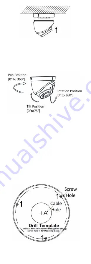
Figure 7 3-axis Adjustment 

1).


Hold the camera body and rotate the 
enclosure to adjust the pan position [0° to 
360°]. 

2).


Move the camera body up and down to 
adjust the tilt position [0° to 75°]. 

3).


Rotate the camera body to adjust the 
rotation position [0° to 360°]. 

3.2


Type II Camera Ceiling Mounting 

Steps 

1.


Paste the drill template to the ceiling. 

2.


Drill the screw holes and cable hole (optional) in 
the ceiling according to the drill template. 


Figure 8 Drill Template 


Summary of Contents for DS-2CE57U8T-VPIT

Page 1: ...including among others wordings pictures graphs are the properties of Hangzhou Hikvision Digital Technology Co Ltd or its subsidiaries hereinafter referred to be Hikvision This user manual hereinafter referred to be the Manual cannot be reproduced changed translated or distributed partially or wholly by any means without the prior written permission of Hikvision Unless otherwise stipulated Hikvisi...

Page 2: ...ause harmful interference 2 This device must accept any interference received including interference that may cause undesired operation 1 1 3 EU Conformity Statement This product and if applicable the supplied accessories too are markedwith CE and comply therefore with the applicable harmonized European standards listed under the Low Voltage Directive 2014 35 EU the EMC Directive 2012 19 EU WEEE D...

Page 3: ...Refer to technical specifications for detailed information The camera is powered by an external DC power supply 12 VDC 1 A that complies with the LPS and the output current of this external DC power supply must be no more than 6 A Do not connect multiple devices to one power adapter to avoid overheating or a fire hazard caused by overload Make sure that the plug is firmly connected to the power so...

Page 4: ...iquid while in use for non waterproof devices While in delivery the camera shall be packed in its original packing or packing of the samematerial 1 1 8 Mark Description Table 0 1 Mark Description Mark Description DC Voltage 2 Introduction 2 1 Product Features The camera is applicable for both indoor and outdoor conditions Application scenarios include roads warehouses underground parking lots bars...

Page 5: ... mount If the wall is cement insert expansion screws before installing the camera If the wall is wooden use self tapping screw to secure the camera If the product does not work properly contact your dealer or the nearest service center Do NOT disassemble the camera for repair or maintenance yourself 3 1 Type I Camera Installation Before you start Both wall mounting and ceiling mounting are suitabl...

Page 6: ...er of the drill template when adopting the ceiling outlet to route the cable 4 Secure the mounting base to the ceiling with the supplied screws Figure 5 Fix the Mounting Base to the Ceiling Notes The supplied screw package contains self tapping screws and expansion bolts For a cement wall ceiling expansion bolts are required to fix the camera For a wooden wall ceiling self tapping screws arerequir...

Page 7: ...get an optimum angle Figure 7 3 axis Adjustment 1 Hold the camera body and rotate the enclosure to adjust the pan position 0 to 360 2 Move the camera body up and down to adjust the tilt position 0 to 75 3 Rotate the camera body to adjust the rotation position 0 to 360 3 2 Type II Camera Ceiling Mounting Steps 1 Paste the drill template to the ceiling 2 Drill the screw holes and cable hole optional...

Page 8: ...e Mounting Base 5 Route the cables through the cable hole optional or the side opening 6 Connect the corresponding cables such as power cord and video cable 7 Power on the camera to check if the monitor image is at an optimum angle If not adjust the camera according to the figure below to get an optimum angle Figure 2 9 Type 11 Camera 2 Axis Adjustment 1 Loosen the tilt adjusting screw to adjust t...

Page 9: ...e Call the menu by clicking the button on the PTZ Control interface or call preset No 95 Steps 1 Connect the camera to the TVI DVR and the monitor as shown TVI DVR Figure 13 Connection 2 Power on the analog camera TVI DVR and the monitor to view the image on the monitor 3 Click PTZ Control to enter the PTZ Control interface 4 Call the camera menu by clicking button or call preset No 95 Ca m Mo nit...

Page 10: ...ck left right direction button to adjust the value of the selected item 4 1 Video Format You can set frame rate as 8 MP 12 5 fps 8 MP 15 fps 5 MP 20 fps 4 MP 25 fps 4 MP 30 fps 1080p 25 fps or 1080p 30 fps 4 2 Language Supports English 4 3 Settings 4 3 1 Exposure Exposure describes the brightness related parameters which can be adjusted by Brightness Exposure Mode AGC and Slow Shutter Figure 15 Ex...

Page 11: ...htness level of the whole image and provides clear images with details When WDR is selected as the exposure mode you can set it as low medium high or off AGC Automatic Gain Control Optimizes the clarity of the image in poor light conditions The AGC level can be set to High Medium or Low Select Off to disable the AGC function Note The noise will be amplified when AGC is on Slow Shutter Slow Shutter...

Page 12: ...lor in day mode all the time B W The image is black and white all the time and the IR light turns on in poor light conditions Auto The image switches from color to B W or from B W to color automatically according to the lighting conditions Click Iris to enter the submenu you can turn on off the IR Light and set the value of Smart IR in this menu Figure 17 Day Night IR Light You can turn on off the...

Page 13: ...gure 18 Video Settings Contrast This feature enhances the difference in color and light between parts of an image You can set the Contrast value from 1 to 10 Sharpness Determines the amount of detail an imaging system can reproduce You can set the Sharpness value from 1 to 10 Saturation Adjust this feature to change the saturation of the color The value ranges from 1 to 10 3D DNR Digital Noise Red...

Page 14: ...ordinary environment and the image appears hazy Enabling the defog function can enhance the subtle details to display clear images 4 3 5 Factory Default Click Iris to enter the submenu and click OK to reset all the settings to the factory default Click Cancel to disregard the reset settings 4 3 6 Save Exit Move the cursor to Save Exit and click Iris to save the settings and exit the menu ...

Reviews: