background image

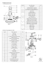
Fiberglass Filter Structure

Key No.

Product Description 

Qty

1

Air Release Valve

1

Oil Pressure Gauge with O-ring (40 psi)

1

Connector for Pressure Gauge/Stopper

1

3

03013003 M8 Nut*12Pc; 03012003 M8 Washer*12Pc

1

4

Lid (Grey Color)

1

5

Filter Neck Gasket

1

700B F e  Ta  W h Ba e

1

800 F e  Ta  W h Ba e

1

900 F e  Ta  W h Ba e

1

7

2.0" Side Mount Valve

1

8

Connector Plate Side Mount

1

700B T   a   f  he 

e   a  

e

1

800 T   a   f  he 

e   a  

e

1

900T   a   f  he 

e   a  

e

1

700B B

  a   f  he 

e   a  

e

1

800 B

  a   f  he 

e   a  

e

1

900 B

  a   f  he 

e   a  

e

1

11

Laterals (233mm)

8

700B A  Ve  P e

1

800 A  Ve  P e

1

900 A  Ve  P e

1

13

Water Drain set

1

Item No.

Product Description 

Qty

1

Handle (Big)

1

2

Pin for Handle

1

3

Washer for Handle

1

4

2.0" Side Mount Valve Squareness Lid (White)

1

5

M6*32 Screw with Nut

10

6

Connector for Pressure Gauge/Stopper

1

7

Drain Plug with O-ring

1

8

Oil Pressure Gauge with O-ring (40psi)

1

9

O-ring for 2.0" Union

8

10

2.0" Connector (White)

3

11

2.0" Union (A/E)

3

12

2.0" Union Nut (White)

3

13

O-ring for 2.0" Valve Lid

1

14

Washer for spring

1

15

O-ring for 2.0" Valve Rotor

2

16

Spring

1

17

2.0" Valve Rotor

1

18

Spider Gasket

1

19

2.0" Side Mount Valve Bottom Body(White)

1

20

Sight Glass With O-ring

1

21

O-ring for Union tale

1

22

2.0" Union Tale (White)

1

23

2.0" Union Nut (Black)

2

24

O-ring for Plug

1

25

2.0" Side Mount Valve Plug (White)

2

26

2.0" Elbow Tube (White) 183mm

1

27

2.0" Union Adaptor (Metric)

1

12

2. Multiport Valve Replacement Parts

1. Filter Replacement Parts

2

6

9

10

Figure 2 

Figure 3 

Summary of Contents for HT-VS525

Page 1: ...Fiberglass Filter Side Mount Series USER MANUAL ...

Page 2: ...ly directed by the filter control valve to the top of the filter tank As the pool water is pumped through the filter dirt particles are rapped by the sand bed and filtered out The cleaned Pool water is returned from the bottom of the filter tank through the control valve and back to the pool through the piping system This entire sequence is continuous and automatic and provides for total recircula...

Page 3: ...ewdriver handle to help seat the valve flange clamp 4 Set a return to the pool pipe connection to control the valve opening marked RETURN and complete other necessary plumbing connections suction as lines to the pump waste etc 5 Perform the electrical connections to the pump following the pump manual 6 Make sure all the pipe connections are tight and there are no leakages 1 Make sure the correct a...

Page 4: ...dle Big 1 2 Pin for Handle 1 3 Washer for Handle 1 4 2 0 Side Mount Valve Squareness Lid White 1 5 M6 32 Screw with Nut 10 6 Connector for Pressure Gauge Stopper 1 7 Drain Plug with O ring 1 8 Oil Pressure Gauge with O ring 40psi 1 9 O ring for 2 0 Union 8 10 2 0 Connector White 3 11 2 0 Union A E 3 12 2 0 Union Nut White 3 13 O ring for 2 0 Valve Lid 1 14 Washer for spring 1 15 O ring for 2 0 Val...

Page 5: ...Gasket 1 The spider gasket is loose or damaged Please see Figure 3 Item No 18 Spider Gasket 1 Check if the spider gasket is loose or not adjust it 2 Item No 14 Washer for spring is damaged 2 Replace item No 14 washer for spring Please see Figure 3 2 The laterals are damaged Please see Figure 2 item No 11 Laterals 2 If water outlet pipe also leaking that means the laterals are broken please replace...

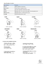
Page 6: ... pool Function and Installation Scheme I Filtration of Medium i e Water Pool Pump Valve to filter filter Valve from filter Pool II Drainage of Pool with Pump Pool Pump Valve Canal III No Circulation Do not operate pump Pool Pump Valve IV Cleaning of Filter Medium i e Sand in upstream reserved flow in filter Pool Pump Valve from filter filter Valve to filter Waste V Recirculation of Fluid Without F...

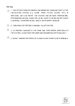
Page 7: ... BECOME PRESSURIZED PRESSURIZED AIR CAN CAUSE THE LID OR VALVE TO BE BLOWN OFF WHICH CAN RESULT IN SEVERE INJURY DEATH OR PROPERTY DAMAGE 2 TURN PUMP OFF BEFORE CHANGING VALVE POSITION 3 TO PREVENT DAMAGE TO THE PUMP AND FOR PROPER OPERATION OF THE SYSTEM CLEAN PUMP STRAINER AND SKIMMER BASKET REGULARLY 4 DO NOT UNSCREW SCREWS OF FLANGE CLAMP WHILE PUMP IS RUNNING ...

Reviews: