background image

Rev. B 07-2013

32

MTEC.3800.GB-B-1 Operation and maintenance WSA series English  

WSA

 Water chiller

If the fluid in the circuit contains anti-freeze, it MUST not be allowed to run away to drain. It must  be collected for 
possible re-cycling or for correct disposal.

4.17 Filling the hydraulic circuit

4.18  Emptying the installation

Before filling, check that the installation drain valve is closed.

• 

Open all pipework, heat pump and terminal unit air vents.

• 

Open the shut off valves.

• 

Begin filling, slowly opening the water valve in the filling group outside the unit.

• 

When water begins to leak out of the terminal air vent valves, close them and continue filling until the pressure gauge indicates a pressure 

• 

of 1.5 bars.

The installation should be filled to a pressure of between 1 and 2 bars. It is recommended that this operation be repeated after the unit 
has been operating for a number of hours (due to the presence of air bubbles in the system). The pressure of the installation should be 
checked regularly and if it drops below 1 bar, the water content should be topped-up. If frequent top-ups are required, check all connections 
for leaks.

Before emptying, place the mains switch in the “Off” position.

• 

Make sure the filling group valve is closed.

• 

Open the drainage valve outside the unit and all the installation and terminal air vent valves.

• 

Summary of Contents for WSA Series

Page 1: ...ork on the unit RETAIN FOR FUTURE REFERENCE Incorporated in this document are the following Declaration of conformity Technical manual Dimensional drawing Wiring diagrams TECHNICAL MANUAL WATER CHILLERS WSA SERIES MTEC 3800 GB B 1 Operation and maintenance WSA series English Rev 07 2013 Original Instructions ...

Page 2: ...l inquiries regarding the use of its products HIDROS S p A follows a policy of continuous product development and improvement and reserves the right to modify specifications equi pment and instructions regarding use and maintenance at any time without notice Declaration of conformity We declare under our own responsibility that the below equipment complies in all parts with the CEE and EN directive...

Page 3: ...limits 19 3 6 Correction tables 20 3 7 Sound data 21 4 INSTALLATION 21 4 1 General safety guidelines and and use of symbols 21 4 2 Workers health and safety 22 4 3 Personal protective equipment 22 4 4 Inspection 22 4 5 Storage 23 4 6 Unpacking 23 4 7 Lifting and handling 23 4 8 PLocation and minimum technical clearances 24 4 9 Installation of rubber vibration dampers KAVG 25 4 10 Serial interface ...

Page 4: ...ustic signal silencing 47 6 7 Alarm reset 47 6 8 Display alarm history 47 7 MAINTENANCE OF THE UNIT 48 7 1 General warnings 48 7 2 Access to the unit 48 7 3 Periodical checks 48 7 4 Refrigerant circuit repair 49 8 DECOMMISSIONING 50 8 1 Unit Isolation drain down 50 8 2 Disposal recovery and recycling 50 8 3 RAEE directive only for EC countries 50 9 DIAGNOSIS TROUBLESHOOTING 50 9 1 Fault finding 50 ...

Page 5: ...tructions are intended to provide the information required for the selection installation use and maintenance of the unit They have been prepared in accordance with the European Union laws and with the technical standards in force at the date of issue of the instructions The instructions contain all the necessary information to prevent any reasonably foreseeable misuse The manual must be kept in a...

Page 6: ...t Avoid any contact use protective gloves Internal component electric cables and metallic parts Electrocution severe burns Defect in the supply cable in sulation live metallic parts Adequate protection of power ca bles ensure correct earthing of all metal parts External to unit unit enclosure Poisoning severe burns Fire due to short circuit or overheating of the supply ca ble external to unit Size...

Page 7: ...phic symbol added to a yellow triangle with black edges indicates danger ACTION REQUIRED A white symbol inserted in a blue circle indicates an action that must be done to avoid a risk The graphic symbol warning is qualified with additional safety information text or other symbols Safety symbols combined in accordance with ISO 3864 2 1 7 General Description of Symbols Used Safety symbols combined in...

Page 8: ...ribed in this manual that could create an electrical hazard MOVING PARTS The symbol indicates those moving parts of the unit that could create risk HOT SURFACES The symbol indicates those components with high surface temperature that could create risks SHARP SURFACES The symbol indicates components or parts that could cause stab wounds EARTH CONNECTION The symbol identifies Earthing connection poin...

Page 9: ... Date de fabrication 41 5 22 1 18 01 2012 MTEC 3800 GB B 1 Operation and maintenance WSA series English WSAWater chiller The unit is not suitable for operations in environments excessively dusty or potentially explosive atmospheres where there are vibrations where there are electromagnetic fields where there are aggressive atmospheres The product label should never be removed from the unit The mach...

Page 10: ... 1 6 Professional exposure limits 2 2 Refrigerant handling The refrigerants used decompose in the lower atmosphere troposphere relatively quickly The decomposed products are highly dispersible and therefore have a very low concentration They do not influence the photochemical smog which is not among the VOC volatile organic compounds as stipulated in the guidelines to the UNECE The constituent refr...

Page 11: ...is lower Always ensure adequate venti lation Avoid contact with open flames and hot surfaces as this can cause toxic and irritating decomposition products to form Avoid contact between liquid refrigerant and the eyes or skin Ensure suitable personal protection especially respiratory protection during cleaning operations If deemed safe isolate the source of the leak If the leakage is small and if ad...

Page 12: ...nding for thermal overload protection They are mounted within the casing The crankcase heater is always energised when the compressor is in stand by Access to the compressors is by removal of a front panel and maintenance of the compressors is possible whilst the unit is operating 3 1 4 Source heat exchangers The source heat exchangers are braze welded plates made with stainless steel AISI 316 Mod...

Page 13: ...tional life of the units component s Use ofACTIVE auto adaptive Control enables the minimum water content to be reduced from the traditional 12 15 l kw to 5 l kw Afurther benefit of the reduced water requirement is that units can be used in installations without a buffer tank thereby reducing the space requirements thermal losses and costs 3 1 8 Control and protection devices All units are supplied...

Page 14: ...arting current down to maximum 40 of the nominal peak value The device can only be installed in the factory 3 3 6 Pressure gauges MAML These enable the standing charge and the operating pressures to be monitored 3 3 7 Pressostatic valve kit Cooling versions only VPSF Used to reduce the water consumption on the source heat exchanger 3 3 8 Remote control panel PCRL This panel can be mounted up to 50...

Page 15: ...17 1 22 11 3 15 16 22 25 31 34 n 1 1 1 1 1 1 1 1 1 1 1 1 1 1 1 1 1 1 1 1 dB A 51 52 52 54 54 60 60 62 64 64 dB A 43 44 44 46 46 52 52 54 56 56 MTEC 3800 GB B 1 Operation and maintenance WSA series English WSAWater chiller 3 4 Technical data Performance refer to the following conditions 1 Cooling User water temperature in out 12 7 C source water temperature in out 30 35 C Unit without pressure valv...

Page 16: ...itions 5 EV version source heat exchanger temperature 50 C in out temperature 12 7 C 2 Sound power level in accordance with ISO 9614 LS version 3 Sound pressure level at 10 mt from the unit in free field conditions direction factor Q 2 calculated in accordance with ISO 9614 LS version Versions WSA EV Cooling capacity 7 Compressor input power 7 Water flow 7 User water pressure drops Peak current Max ...

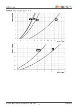
Page 17: ...0 70 80 90 100 110 4 5 6 7 8 9 10 11 12 06 14 16 08 21 26 10 41 31 36 MTEC 3800 GB B 1 Operation and maintenance WSA series English WSAWater chiller Water flow m3 h Water flow m3 h Water flow m3 h Pressure drop kPa Pressure drop kPa Pressure drop kPa 3 4 2 Source and user heat exchanger water pressure drops ...

Page 18: ...5 6 6 5 7 7 5 8 14 16 21 26 10 20 30 40 50 60 70 3 4 5 6 7 8 9 10 31 36 41 MTEC 3800 GB B 1 Operation and maintenance WSA series English WSAWater chiller 3 4 3 Partial heat recovery water pressure drops Water flow m3 h Water flow m3 h Pressure drop kPa Pressure drop kPa ...

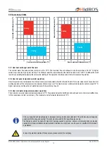
Page 19: ... which results in a ΔT of 8 C Insufficient flow will result in evaporating temperatures that are too low leading to the operation of safety devices that will prevent unit operation 3 5 2 User hot water temperature winter operation Once the system is on temperature the minimum user water temperature should not be less than 30 C Lower values could cause incorrect working operation of the compressor an...

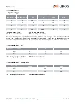
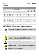
Page 20: ...n factor IPCF Input power correction factor 3 6 1 Operation with glycol 3 6 2 Correction tables different T 3 6 3 Correction tables different Fouling factors CCF Capacity correction factor IPCF Input power correction factor WFCF Water flow correction factor PDCF Pressure drops correction factor The water flow rate and pressure drop correction factors are to be applied directly to the values given wi...

Page 21: ... STANDARD VERSIONS without compressor jackets and compressor vane insula tion is approx 1 5 dB A higher than the equivalent low noise versions LS 3 7 Sound data LOW NOISE VERSION LS Octave bands Hz Lw Sound power level according to ISO 9614 Lp Sound pressure level measured at 10 mt from the unit in free field conditions direction factor Q 2 according to ISO 9614 Before undertaking any task the oper...

Page 22: ...ing or servicing the unit it is necessary to strictly follow the rules reported on this manual to conform to all the specifications of the labels on the unit and to take any possible precautions of the case Not observing the rules reported on this manual can create dangerous situations After receiving the unit immediately check its integrity The unit left the factory in perfect conditions any event...

Page 23: ...sable to leave packaged units during handling and remove it before the installation The packaging must be removed carefully to prevent any possible damage to the machine The materials constituting the packaging may be different in nature wood cardboard nylon etc 4 7 Lifting and handling When unloading the unit it is strongly recommended that sudden movements are avoided in order to protect the ref...

Page 24: ...fting systems required to perform repairs during warranty period The installation site should be chosen in accordance with EN 378 1 and 378 3 standards When choosing the installation site all risks caused by accidental refrigerant leakage should be taken into consideration 4 8 Location and minimum technical clearances All models are designed and built for indoor installations it is a good idea to ...

Page 25: ...ERIAL INTERFACE CARD 4 10 Serial interface card RS485 INSE Supervision system interface serial board MODBUS RS485 available only The installation of the card will allow the unit to be plugged in and connected to a system with MODBUS protocol This system allows you to remotely monitor all parameters of the unit and change their values The serial interface board is normally fitted at the factory wher...

Page 26: ... the source circuit there is a risk of freezing of the source heat exchanger in this case the warranty expires immediately The activation of the modulating valve V2MO shows a selector used to vary the type of signal and the sense of rotation of the valve itself Tampering can undermine the correct operation of the valve precluding security 4 12 Hydraulic connections The water pipe work must be inst...

Page 27: ... exchangers of the unit should not be fall below Δt 8 C measured at the following conditions Heating mode 7 C Dry bulb ambient temperature 35 C water outlet temperature Cooling mode 35 C dry bulb ambient temperature 7 C water outlet temperature 4 13 Chemical characteristics of the water The system is to be filled with clean water and vented after a full flushing operation has been performed the wate...

Page 28: ...ge caused by corrosion clogging and freezing if attributable to lack and or incorrect installation of described safety devices The use of groundwater generally requires approval by the municipality and or the province Check with local authorities The limit values in the table may cause clogging by mud in the pipes and the heat exchanger The maintenance of the quality of ground water is borne by th...

Page 29: ...Rev B 07 2013 29 O N Q N Q O MTEC 3800 GB B 1 Operation and maintenance WSA series English WSAWater chiller 4 16 Hydraulic components User heat exchanger Source heat exchanger Flow Switch ...

Page 30: ... It is ALWAYS recommended to perform an accurate chemical analysis of water by a qualified technician In the case where it is not possible to maintain control the water quality parameters listed above there has to opt for a source hydraulic circuit type 2 System Filling Group Source water Filter Thermometer Flexible Connection Vent Valve User water Filter Circulating pump Manual valve Source modula...

Page 31: ...ly recommended in those installations where it is not possible to maintain control the water quality parameters listed above The installation of the intermediate heat exchanger lead to lower performance of the unit and requires an auxiliary pump Please contact the Company in case of need for sizing of the intermediate heat exchanger System Filling Group Flexible Connection Thermometer User water F...

Page 32: ...ter begins to leak out of the terminal air vent valves close them and continue filling until the pressure gauge indicates a pressure of 1 5 bars The installation should be filled to a pressure of between 1 and 2 bars It is recommended that this operation be repeated after the unit has been operating for a number of hours due to the presence of air bubbles in the system The pressure of the installati...

Page 33: ...by sections location and building structure Piping should be as short as possible in order to reduce pressure drops in refrigerant circuit and the refrigerant charge in the system Lines must be isolated and the maximum admitted pipe length is 30 meters Please contact the Company for any information or before to install the unit beyond the limid described Refrigerant line diameters for EV versions ...

Page 34: ...correction factors Install a collection pit on discharge and return line so that liquid refrigerant when the system is not running can be collected by this pit avoiding its return to compressor heads and possible failure On horizontal pipelines a minimum 1 slope should be allowed in order to drain oil in the proper flow direction Liquid line diameter mm Refrigerant charge g m Liquid line diameter m...

Page 35: ...nto account all the factors that may influence temperature type of insulation length etc Power supply must respect the reported tolerances and limits If those tolerances should not be respected the warranty will be invalidated Flow switches must be connected following the indication reported in the wiring diagram Never bridge flow switches connections in the terminal board Guarantee will be invalida...

Page 36: ...ical data reported below refer to the standard unit without accessories In all other cases refer to the data reported in the attached electrical wiring diagrams The line voltage fluctuations can not be more than 10 of the nominal value while the voltage unbalance between one phase and another can not exceed 1 according to EN60204 If those tolerances should not be respected please contact our Compan...

Page 37: ...connect the visual or audible device between terminals 90 91 92 Contacts 90 91 NC Normally closed Contacts 91 92 NO Normally opened REMOTE CONTROL PANEL The remote control panel replicates all of the functions on the main controller panel and can be connected up to a maximum distance of 50 meters from the unit The panel has to be connected to the unit by 2 wires having diameter 0 75 mm2 The power ...

Page 38: ...uit layout components Source water input probe Liquid receiver Source water output probe Compressor High pressure transducer Water flow switch User water input probe High pressure pressostat User water output probe Low high pressure switch Charging plug Source side Charging plug 1 4 sae r407 Shut off valve Source exchanger User side Desuperheater Source water modulating valve Termostatic valve Pres...

Page 39: ...SHP 2 CH BCO øSC øDC øSC øL øL øL MC DSP EXV VR VR EXV IV øH SFW UT øH øH SFW SO FL NO NC VRV BTO BTI VMAS 1 CHR øSC 1 CHR øSC SLP GLP 2 CH SHP 2 CH GHP BHP 1 CH BCO MTEC 3800 GB B 1 Operation and maintenance WSA series English WSAWater chiller 4 23 3 Refrigerant circuit layout WSA HP 04 21 4 23 3 Refrigerant circuit layout WSA HP 26 40 ...

Page 40: ...that the unit is installed in a workmanlike manner and in accordance with the guidelines in this manual Check that all power cables are properly connected and all terminals are correctly fixed The operating voltage between phases R S T is the one shown on the unit labels Check that the unit is connected to the system earth Check that there is no refrigerant leakage Check for oil stains sign of a po...

Page 41: ...he set point of the control thermostat For A version units units with pumps and storage tank if the pump is noisy slowly close discharge shut off valve until the noise is reduced to normal levels This can occur when the system pressure drop substantially lower than the pump available pressure After several hours of operation check that the sight glass has a green colour core if the core is yellow ...

Page 42: ... of the different temperatures 1 click Bottom line displays Pb1 User inlet water temperature 2 clicks Bottom line displays Pb2 User outlet water temperature 3 clicks Bottom line displays Pb3 refrigerant pressure high pressure in cooling low pressure in he ating mode 4 clicks Bottom line displays Pb4 Finned coil temperature not used In programming mode it allows the user to scroll through the param...

Page 43: ... clicks Bottom line displays Pb3 refrigerant pressure high pressure in cooling low pressure in he ating mode 4 clicks Bottom line displays Pb4 Finned coil temperature not used In programming mode it allows the user to scroll through the parameter codes or to increase values In standard mode it allows the display of the different temperatures in the opposite way to the above arrow In programming mo...

Page 44: ...splay with the message noL no link Electric data can be updated without notice It is therefore necessary to always refer to the wiring diagram provided in the unit The remote control panel is mounted on a panel with 72x56 mm cut out fixed with screw To obtain IP65 protection for the panel use the rubber gasket RGW V optional For wall mounting use the V KIT plastic adapter as illu strated in the pic...

Page 45: ...it in heating mode 14 Icon ON when the bottom display show current time the hours of operation of the loads etc 7 Icon blinking if low pressure alarm is active 15 Icon on when the display show a temperature or a pres sion 8 Icon blinking if high pressure alarm is active 6 1 Switch the unit on 6 USE 6 1 1 Cooling mode To start the unit in heating mode press the key The snowflake icon is on If reques...

Page 46: ...d off never do this using the main isolator this should only be used to discon nect the unit from the power supply when the unit is to be permanently off Isolation will result in no supply for the crankcase heater and on start up the compressor could be seriously damaged When modifying or varying the machine s operating parameters make sure that you do not create situations that conflict with the o...

Page 47: ...FHR PCHR Working hours compressor 1 Working hours compressor 2 only models with 2 com pressors Working hours user water pump Working hours domestic hot water pump DEF Not used dF1 Countdown in seconds to the next defrost cycle the countdown is active if the defrost led is blinking In case the defrost led is off the defrost cycle is not required During the defrost cycle the defrost led is ON 6 5 Pa...

Page 48: ... should be performed in compliance with all requirements of the previous paragraphs All of the operations described in this chapter MUST BE PERFORMED BY TRAINED PERSONNEL ONLY Before commencing service work on the unit ensure that the electric supply is disconnected The top case and dischar ge line of compressor are usually at high temperature Care must be taken when working in their surroundings ...

Page 49: ...cur 7 4 Refrigerant circuit repair For leak detection the system should be charged with nitrogen using a gas bottle with a pressure reducing valve until 15 bar pressure is reached Any leakage is detected using a bubble leak finder If bubbles appear discharge the nitrogen from the circuit before brazing using the proper alloys Site assembled refrigerant circuits must be assembled and maintained care...

Page 50: ... in large quantities in the machine All materials must be recovered or disposed in accordance with national regulations The RAEE Directive requires that the disposal and recycling of electrical and electronic equipment must be handled through a special collection in appropriate centers separate from that used for the disposal of mixed urban waste The user has the obligation not to dispose of the e...

Page 51: ...Find leakage and repair A07 Anti freeze alarm from analog input Too low water temperature Check user temperature set point Check user water flow A08 Source heat exchanger flow switch alarm air water water water unit Presence of air or dirtiness in the user hydraulic system Bleed carefully the user hydraulic system or check and clean the water service A09 Compressor 1 overload Compressor input curren...

Page 52: ...d maintenance WSA series English WSAWater chiller Dimensional drawings WSA 06 08 010 10 DIMENSIONAL DRAWINGS Rp REMOVABLE PANEL Ep ELECTRICAL PANEL Es INPUT POWER IN 1 1 1 4 GF USER WATER INLET OUT 1 1 1 4 GF USER WATER OUTLET IN 3 1 1 4 GF SOURCE WATER INLET OUT 3 1 1 4 GF SOURCE WATER OUTLET WEIGHT WHEN THE UNIT WORKS Modd WEIGHT Kg 06 08 010 100 ...

Page 53: ...ation and maintenance WSA series English WSAWater chiller Rp REMOVABLE PANEL Ep ELECTRICAL PANEL Es INPUT POWER IN 1 1 1 4 GF USER WATER INLET OUT 1 1 1 4 GF USER WATER OUTLET IN 3 1 1 4 GF SOURCE WATER INLET OUT 3 1 1 4 GF SOURCE WATER OUTLET Dimensional drawings WSA 014 016 021 WEIGHT WHEN THE UNIT WORKS Modd WEIGHT Kg 014 016 120 021 130 ...

Page 54: ...OUT U Ø 1 1 4 IN SO Ø 1 1 4 OUT SO Ø 1 1 4 IN D Ø 1 OUT D Ø 1 MTEC 3800 GB B 1 Operation and maintenance WSA series English WSAWater chiller REMOVABLE PANEL ELECTRICAL PANEL INPUT POWER USER WATER INLET USER WATER OUTLET SOURCE WATER INLET SOURCE WATER OUTLET WATER INLET DESUPERHEATER WATER OUTLET DESUPERHEATER WEIGHT WHEN THE UNIT WORKS 026 031 046 041 185 Kg POS WEIGHT Kg G1 55 5 G2 37 G3 55 5 G...

Page 55: ... OUT U Ø 1 1 4 IN SO Ø 1 1 4 OUT SO Ø 1 1 4 IN D Ø 1 OUT D Ø 1 MTEC 3800 GB B 1 Operation and maintenance WSA series English WSAWater chiller REMOVABLE PANEL ELECTRICAL PANEL INPUT POWER USER WATER INLET USER WATER OUTLET SOURCE WATER INLET SOURCE WATER OUTLET WATER INLET DESUPERHEATER WATER OUTLET DESUPERHEATER WEIGHT WHEN THE UNIT WORKS 026 031 046 041 185 Kg POS WEIGHT Kg G1 55 5 G2 37 G3 55 5 ...

Page 56: ...022 Fax 39 049 5806928 Info hidros it www hidros it P IVA e C F 03598340283 R E A PD 322111 REG IMP PD 0359834 028 3 VAT NUMBER IT 03598340283 CAPITALE SOCIALE 1 200 000 00 i v Technical data shown in this booklet are not binding HIDROS S p A shall have the right to introduce at any time whatever modifications necessary to the improvement of the product ...

Reviews: