Hi-Link HLK-RM58S User Manual Download Page 9


6

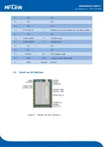
2.2    Wifi connection status indicator pin 

GPIO58  pin  is  used  as  the  indicator  pin  of  the  module’s  wifi  connection  status  in  sta  mode. 

When the module's wifi is connected to the router, GPIO58 will output a high level, otherwise will 
output low level, and other modes will output low level. 


2.3 Socket connection status indicator pin 

The GPIO59 pin is used as the indicator pin of the module socket's connection status. When the 

socket connection is successful, the GPIO outputs a high level, otherwise outputs low level. 


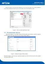
2.4 One-click distribution mode 

For  the  IOT  wifi  module,  based  on  cost  and  performance  considerations,  there  is  no  touch 

screen interactive interface like a mobile phone. Users can see the ap list on the mobile phone and 
click the password to connect to the network. What should I do? One-click configuration is the wifi 
module  in  promiscuous  mode  (can  capture  all  802.11  frames  in  the  air),  APP  sends  the  SSID  and 
password to the wifi module through UDP broadcast or multicast through certain encoding rules, the 
module  parses  out,  and  then  connects  to  the  router.  Install  the  Android  app  HLK-TCPdemo,  then 
select Configure Networking, select the elian mode, then select V5, input the password, click to open 
the  configuration  and  start  the  configuration.  When  the  distribution  network  is  successful,  the 
module will change from double flash to quick flash, indicating network successful connected. 


Figure 4    One-click distribution network 

Summary of Contents for HLK-RM58S

Page 1: ...Shenzhen HI Link Electronic Co Ltd User Manual Version V1 1 Revised date 2017 1 16 Copr by Hi link Electronic Co Ltd...

Page 2: ...t 11 2 10 Application areas 11 3 AT Instructions 11 3 1 Query current module version at ver 12 3 2 Local port operation at CLport 12 3 3 Set up serial Port at uart 11 3 4 Set up DHCP at dhcpc 11 3 5 S...

Page 3: ...ngs 19 4 5 Configuration software description 19 5 Upgrade Introduction 20 5 1 Introduction of Serial Port Upgrade Method 20 5 1 1 Open Serial Port upgrade Software 21 5 1 2 Start to upgrade 21 5 2 In...

Page 4: ...the Internet network without changing any configuration which provides a complete and fast solution for the user s serial port device to transmit the data through the network 1 2 Product Characterist...

Page 5: ...arameters Hardware interface UART IIC PWM GPIO SPI Working voltage 5V GPIO drive capability Max 16ma Working current Continuous send Average value 100mA peak value 120mA In normal mode Average 100mA P...

Page 6: ...3 NC NC 4 UART_RXD1 I Serial port 1 receiving 5 UART_TXD1 O Serial port 1 sending 6 NC NC 7 NC NC 8 NC NC 9 NC NC 10 NC NC 11 NC NC 12 NC NC 13 NC NC 14 NC NC 15 NC NC 16 NC 17 NC NC 18 NC NC 19 NC N...

Page 7: ...NC 28 NC NC 29 NC NC 30 SYS_RST_N I Module reset low level effective reset time 500ms 31 NC NC 32 UART_TXD0 O Serial 0 output 33 UART_RXD0 I Serial 0 input 34 NC NC 35 NC NC 36 GPIO33 I O Wifi indica...

Page 8: ...1 The wifi indicator flashes twice periodically indicates that the module is in the one click distribution mode 2 The wifi indicator flashes thirdly periodically indicates that the module is in the st...

Page 9: ...ere is no touch screen interactive interface like a mobile phone Users can see the ap list on the mobile phone and click the password to connect to the network What should I do One click configuration...

Page 10: ...mode Figure 5 Set to one click distribution mode 2 5 Web distribution function When the module is in ap mode input 192 168 16 254 in the browser and then input the account and password admin later ent...

Page 11: ...ata into wifi data to achieve the purpose of networking 2 7 Serial to WIFI AP Figure 8 Module work as ap In AP mode mobile phone PC or other wifi devices can be connected to RM58S module through wifi...

Page 12: ...ed as transparent data Figure 9 Serial port mode conversion 2 9 Serial port network data conversion 2 9 1 Module as TCP Server Figure 10 TCP Server In this mode the module listens to the specified por...

Page 13: ...nnection can result in active re connection of the module 2 9 3 Module as UDP Server Figure 12 UDP Server In this mode the module opens the local designated port once it receives the data sent to the...

Page 14: ...ment Smart card terminals wireless POS machines handheld devices and so on 3 AT Instructions Instruction format in AT instruction mode the system can be configured through the AT instructions of the s...

Page 15: ...the local port to port 8080 at CLport at CLport 8080 Description Query local port 3 3 Set up serial Port at uart Command Type Grammar Return and description EO at uart 115200 8 n 1 at uart 115200 8 n...

Page 16: ...ode Query Command at mode at mode client Description client server 3 7 Set up remote IP when modules work as client at remoteip Command Type Grammar Return and description EO at remoteip 192 168 11 10...

Page 17: ...d password of the module Query Command at wifi_conf at wifi_conf HI LINK_5FE8 none 12345678 Description Query the ssid and password of the module 3 12 Set up socket connection Protocol at remotepro Co...

Page 18: ...40 D6 3C 15 5F E8 Description query module mac address 3 16 Set up frame length at uartpacklen Command Type Grammar Return and description EO at uartpacklen 64 at uartpacklen 64 ok Description Set the...

Page 19: ...col at mode r n Query tcp connection mode at uart r n Query the serial port parameter at uartpacklen r n Query serial port frame length at uartpacktimeout r n Query serial port frame time at ver r n Q...

Page 20: ...ro tcp r n Set socket s connection methods at mode client r n Use client mode to connect to the remote server at uart 115200 8 n 1 r n Set the serial port parameter at uartpacklen 64 r n Set the frame...

Page 21: ...connection methods at mode server r n Socket as a server to connect at uart 115200 8 n 1 r n Set serial port parameters at uartpacklen 64 r n Set the frame length at uartpacktimeout 10 r n Set the fra...

Page 22: ...ally and all configuration parameters are factory configured More functions are configured with the serial port software and the serial port on the left side of the software automatically generates th...

Page 23: ...older there is a img file upgrade software mainly read the files inside to upgrade There are three files in the img folder where HLK RM58S img and HLK RM58S b 1 00 1 20180611182552 Img file contents a...

Page 24: ...the space bar press and hold the ES0 GPIO0 and RST SYS_RST_N buttons at the same time then release the button RST 0 5s then release the button ES0 computer side software will automatically upgrade th...

Page 25: ...ecause you need to input the ip of the module when upgrading you can go to the router to find the corresponding ip of the module or use HLK RM58S_Discover to search the corresponding ip for the module...

Page 26: ...aded successfully Figure 21 Upgrade completed If your computer turns on a dual network card you may not be able to upgrade and you will need to shut down a network card if it is generated by the insta...

Page 27: ...ctions for host product manufacturers according to KDB 996369 D03 OEM Manual v01 2 2 List of applicable FCC rules FCC Part 15 407 2 3 RF exposure considerations This equipment complies with the FCC RF...

Page 28: ...encouraged to try to correct the interference by one or more of the following measures Reorient or relocate the receiving antenna Increase the separation between the equipment and receiver Connect the...

Reviews: