background image

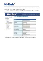
2. Pc can connect with module through Ethernet, ip: 192.168.16.123/255.255.255.0. Using 

Browser to access to 192.168.16.254. Username / password: admin / admin. 

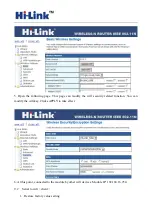
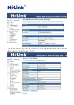
3. Open the following page, set to Ethernet Converter mode.Click on the APPLY to take effect. 


4. Open the following page.Click APPLY to increase AP information. 


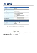
5. Pop-up the following dialog box.Fill in SSID, encryption, key information.Click on the apply 

effect. 

Summary of Contents for HLK-RM04

Page 1: ...HLK RM04 User Manual ETHERNET WIFI Full Function Serial Network Wireless Module...

Page 2: ...ORK PARAMETER 6 4 PARAMETER CONFIGURATION DIRECTION 6 5 WEB CONFIGURATION 7 5 1 WEB NETWORK CONFIGURATION 7 5 2 WEB SERIAL CONFIGURATION 7 6 SERIALAT COMMAND CONFIGURATION 8 6 1 ACCESS TO AT COMMAND M...

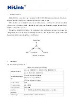
Page 3: ...configuration data can be transmitted through the Internet network Provide a quick solution for the user s serial devices to transfer data via Ethernet Picture1 F structure 2 Summarize 2 1 Technical...

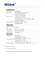
Page 4: ...B software upgrade Serial to Network Maximum transmission rate 230400bps TCP connection Max connection number 20 UDP connection Max connection number 20 Serial baud rate 50 230400bps Other Parameters...

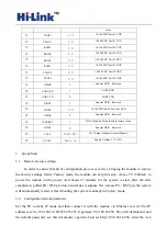
Page 5: ...ction Direction Explanation 1 VCC5V A Supply Voltage 5V 10 2 GND GND Analogue Ground 3 WIFILED O WLAN Activity LED 4 VO3 3 I 3 3V Output Suuport Atmost 300mA 5 LINK1 I O 10 100 PHY Port 1 activity LED...

Page 6: ...In Supply Voltage 5V 10 3 Quick Start 3 1 Restore factory settings In order to ensure that all of configuration process is correct bringing the module to restore the factory settings firstly Factory...

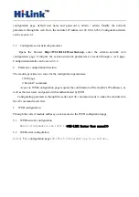
Page 7: ...guration direction The module provides two ways for the configuration parameters 1 Web page 2 Serial AT command Access to WEB configuration page requires the confirmation of the module s IP addresses...

Page 8: ...he Lenth of Serial Framing rial Framing Timeout The time of Serial Framing twork Mode choose Client Server or none ess r exmpale 192 168 11 245 or www hlktech com pa Serial bit Fo Se Se Ne Remote Serv...

Page 9: ...ata transmis th 6 Serial AT command configuratio Access to AT command mode Module in network fault such as fault allocation situation will automatically exit the transparent transmission mode enter AT...

Page 10: ...e factory settings By keeping the ES RST pin low level time greater than Trst parameter values see the following 4 7 Restore factory Settings Support the following way 1 Through the Web page 2 Factory...

Page 11: ...Select the appropriate firmware click apply upgrades Wait a 9 on will give some simple examples to use the different functions of a typical 6 123 255 255 255 0 Browser ADIO OFF button to turn off wif...

Page 12: ...ou to modify the the LAN port parameters Set Ethernet ip address gateway dns server information click apply to take effect 5 At this moment you must use new ip address to access the web page 9 1 Seria...

Page 13: ...wser visits 192 168 16 254 Username password admin admin 3 Open the following page dhcp type opens the server function Click APPLY enable This page allows you to modify the the LAN port parameters 4 O...

Page 14: ...odify the wifi security related function You can modify the wifi key Clicks APPLY to take effect 6 At this point connected to the module by other wifi devices Module IP 192 168 16 254 9 2 Serial to wi...

Page 15: ...o 192 168 16 254 Username password admin admin 3 Open the following page set to Ethernet Converter mode Click on the APPLY to take effect 4 Open the following page Click APPLY to increase AP informati...

Page 16: ...6 Open the following page This page can modify the WiFi security related function You can modify the WiFi key Click on the APPLY effect...

Page 17: ...7 Open the following page view IP information of the module Wan IP address is the ip If no IP address appears it means disconnected to AP...

Page 18: ...Appendix A document revision record Version number Revision range Date 1 00 Draft version 2012 9 10...

Reviews: