7.2.2014
Mutant Bassdrum assembly tips v1.05
PG3
hexinverter.net electronics, 2014
STEP 3: Control surface assembly
Putting together the control surface is arguably the most challenging part of this project so I recommend
taking your time. If you have been working for awhile, put down the soldering iron and go take a break and
clear your mind. I recommend this order of assembly:
1.
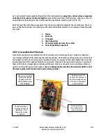
Take the control PCB off of the PCB stack in order to work on it alone
2.
Cut the little metal tab off each potentiometer (this depends on the type of pot you use)
3.
Put everything loosely in place on the control PCB (don’t solder yet)
4.
Place some washers/spacers on the pots to match the panel height
5.
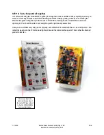
Remove the protective film on the panel and place it on the components
6.
Finger tighten all of the nuts onto the panel. The jacks should be
flat against the panel so they raise
off the PCB a bit.
7.
Solder one leg of each pot and then reheat, pushing the pots flat against the PCB
8.
Solder one leg of each jack and then reheat, pushing the jack flat against the panel
9.
Solder one leg of each part and reheat, adjusting them to their final position on the panel
10.
Once you are happy with the position of everything, solder everything!
11.
Take a piece of component leg and use it to make a ground lead for each of the 3.5mm jacks.
Solder them in place.
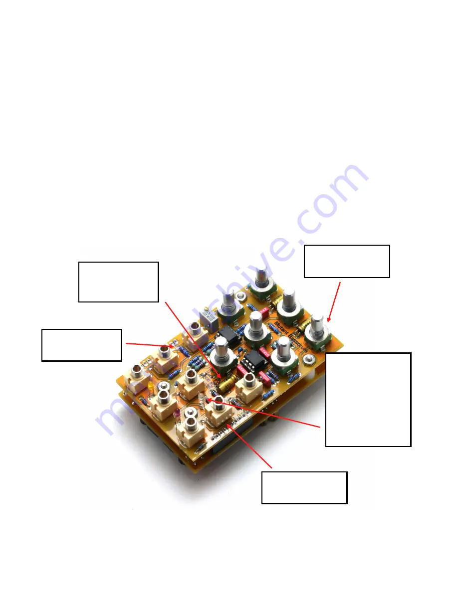
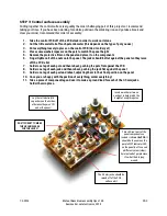
The 3.5mm jacks should be
raised off of the PCB
surface a bit
I used a washer or two on
each pot to help match the
height of everything else
DON
’
T FORGET TO MAKE
THE GROUND LEADS
FOR THE JACKS!
This LED isn’t part of the
panel components so
instead it sits
on the PCB.
It
should be the same as the
purple DIST indicator LED
on the panel, but I’ve used
a different colour (clear)
here instead of purple since
it’s what I had laying
around.
Lay the tall electrolytic
capacitors on their sides,
otherwise they won’t fit
under the panel!


