12|
Aruba AP-5XX Wireless Access Points with ArubaOS FIPS Firmware FIPS 140-2 Level 2 Security Policy
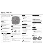
Figure 5 - Aruba AP-500 Series Campus Access Point – Interfaces
DC power interface:
12Vdc nominal, +/- 5%
2.1mm/5.5mm center-positive circular plug with 9.5mm length
USB 2.0 host interface (Type A connector)
Bluetooth 5.0 Low Energy (BLE5.0) and Zigbee (802.15.4) radio:
Bluetooth 5.0: up to 7dBm transmit power (class 1) and -93dBm receive sensitivity (1 Mbps)
Zigbee: up to 6dBm transmit power and -96dBm receive sensitivity
Other Interfaces
Visual indicators (two multi-color LEDs): for System and Radio status
Reset button: factory reset (during device power up)
Serial console interface (
proprietary; optional adapter cable available;
disabled in FIPS mode)
Table 1 -
AP-500 Series Status Indicator LEDs
LED Type
Color/State
Meaning
System Status (Left)
Off
AP powered off
Green - Blinking
Device booting; not ready
Green - Solid
Device ready
Amber - Solid
Device ready; power-save mode (802.3af PoE):
* Single radio
* USB disabled
Green or Amber
Flashing
Device ready, restricted mode:
*
Uplink negotiated in sub optimal speed; or
*
Deep sleep mode
Red
System error condition
Radio Status (Right)
Off
AP powered off, or both radios disabled
Green - Solid
Both radios enabled in access mode
Amber - Solid
Both radios enabled in monitor mode
Green or Amber
Blinking
One radio enabled in access (green) or monitor
(amber) mode, other disabled
Green/Amber
Alternating
Green: one radio enabled in access mode,
Amber: one radio enabled in monitor mode