PAGE 14
© Copyright Hewland Engineering Limited 2001-2008
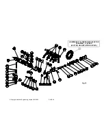
O p t i o n a l L i g h t e n e d
Parts
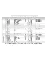
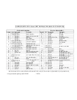
The following lightened parts are available for the FTR
3/
The second adjustable factor is how
tightly the plate stack is compressed
on assembly (known as static
preload). Included in the plate stack is
a preload spacer. The preload torque
is measured between the side bevel
gears, by holding one side bevel gear
stationary, and measuring the torque
required to turn the other using tools
SK-1710-A & SK-1710-B. When the
diff is assembled, the preload torque
must be at least 10 lbs.ft, but can be
much greater if required. New plates
‘run in’ so a higher preload is advised
than with used plates. To assist in de-
termining the size of the preload
spacer
set up shims may be used. They are
available in 5 different sizes,
.003” .005” .008” .010” .015”
4/
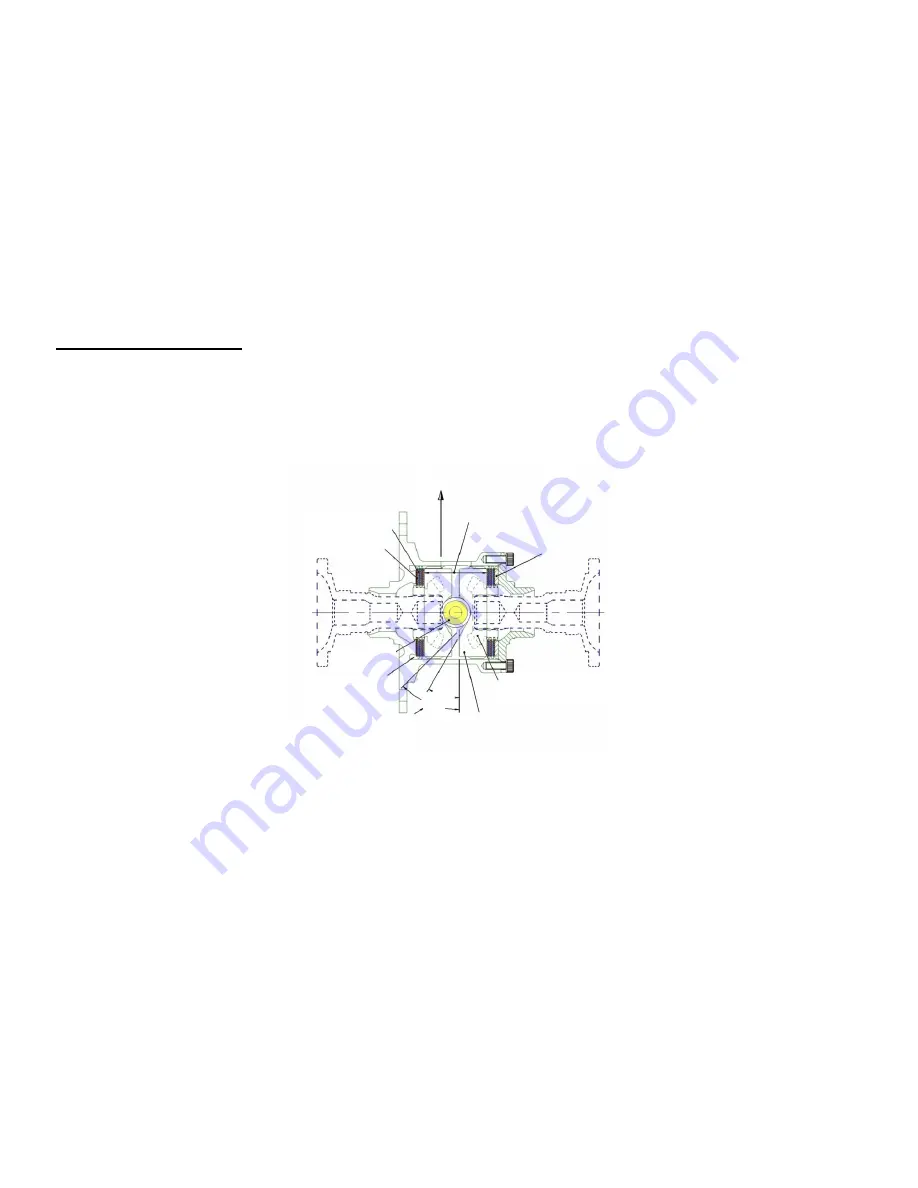
The final adjustment is simply to re-
order the plate stack so as to change
the number of relatively rotating
faces. The diagram shows the stack
setup with the maximum 12 working
faces. Standard stack may be
shuffled to give as few as 2 working
faces.
1
The side bevel gears thrust apart to
clamp the plates as they transmit
the driving power. This is a feature
of the gear geometry, and is not
adjustable.
2
The ramp angles cut on the side
ring gears have an effect on how
much of the transmitted torque is
converted into sideways (clamping)
force onto the plates. For example,
on the drive side ramp, 45 degrees
transmits less sideways force than
30 degrees. Likewise on the coast
side ramp, an 80 degree angle will
transmit little or no clamping force
onto the plates, whereas a 45
degree angle will transmit a much
greater force. Side ring gears are
available with many different drive/
coast ramp angle combinations.
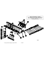
Fig.5
POWERFLOW DIFFERENTIAL
This powerflow differential unit is designed with versatility as it's major asset. Many factors will contribute to the settings required. A car
with good traction and low power, may require a completely different arrangement to that of a car with poor traction and high power.
There are 10 friction plates within the unit 4 splined to the diff casing, and 6 splined to the side bevel gears. Slip limiting is dependant on
the friction resistance between these plates, and is affected by clamping the plates together.. Four factors contribute to the total friction
torque between the plates :-
Clutch Plates
Core Plates
Dir
ec
tion of
Car
Planet Gear
6 Working Faces
per Side
Right Hand Side
Ring Gear
Right Hand Side
Bevel Gear
30º
40º
Greater angle transmits
less thrust onto plates
Preload Spacer
Direction of
force on plates
Fig.5
Summary of Contents for FTR
Page 2: ...PAGE 2 Copyright Hewland Engineering Limited 2001 2008 This page left intentionally blank ...
Page 4: ...PAGE 4 Copyright Hewland Engineering Limited 2001 2008 This page left intentionally blank ...
Page 27: ...PAGE 27 Copyright Hewland Engineering Limited 2001 2009 6 SPEED VARIABLE PARTS ...
Page 47: ...PAGE 47 Copyright Hewland Engineering Limited 2001 2009 5 SPEED VARIABLE PARTS ...
Page 49: ...PAGE 49 Copyright Hewland Engineering Limited 2001 2009 Fig 23 BEARING CARRIER OPTIONS ...
Page 64: ...PAGE 64 Copyright Hewland Engineering Limited 2001 2008 RAMP ORIENTATION Fig 37 ...
Page 65: ...PAGE 65 Copyright Hewland Engineering Limited 2001 2009 GEARBOX TOOLING Fig 38 ...
Page 68: ...PAGE 68 Copyright Hewland Engineering Limited 2001 2008 Fig 39 ...
Page 69: ...PAGE 69 Copyright Hewland Engineering Limited 2001 2009 Fig 40 ...
Page 70: ...PAGE 70 Copyright Hewland Engineering Limited 2001 2008 Fig 41 ...
Page 71: ...PAGE 71 Copyright Hewland Engineering Limited 2001 2009 Fig 42a OUTPUT FLANGE VARIATIONS ...
Page 72: ...PAGE 72 Copyright Hewland Engineering Limited 2001 2008 Fig 42b OUTPUT FLANGE VARIATIONS ...
Page 73: ...PAGE 73 Copyright Hewland Engineering Limited 2001 2009 Fig 42c OUTPUT FLANGE VARIATIONS ...
Page 74: ...PAGE 74 Copyright Hewland Engineering Limited 2001 2008 2nd JUNE 2005 Fig 43 ...
Page 82: ...PAGE 82 Copyright Hewland Engineering Limited 2001 2008 ...
Page 83: ...PAGE 83 Copyright Hewland Engineering Limited 2001 2009 gear b o x They a r e d i ...
Page 84: ...PAGE 84 Copyright Hewland Engineering Limited 2001 2008 19th July 2004 ...
Page 85: ...PAGE 85 Copyright Hewland Engineering Limited 2001 2009 25th January 2005 Fig 47 ...


