


5
M
OUNTING
Y
OUR
R
ECEIVER
1. Determine the receiver location, keeping in
mind the following conditions:
• The receiver will be accessible and
protected from violently thrown materials.
• The status lights will be visible to the
operator.
• The mounting area will accommodate 4
mounting holes in the required pattern.
• There will be enough room for the antenna
and connector plugs or housings.
NOTE: If the receiver will be mounted inside of a
control panel or other enclosure, see
“Installing Your External Antenna (Optional)”
on page 7.
2. Drill 4 mounting holes. See “Drill Pattern and
3. Attach the receiver housing to the desired
mounting surface.
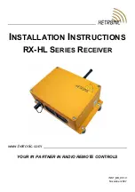
Figure 1: Receiver Dimensions
4. Screw on the antenna provided with the
receiver (by the nut). Do not overtighten.
NOTE: For best reception, position the antenna
straight up and confirm that the surrounding
area is free of obstructions, especially metal.
Figure 2: Drill Pattern and Hardware
Signal
Error
Normal
Operation
107.0 mm
(4.21 in)
161.0 mm
(6.34 in)
Keep area free
of obstructions
Position Antenna
Straight up
4.57”
116mm
Drill 4 Mounting Holes
Hole Size: 9/32” (7mm)
Bolt Size: 1/4” (6mm)
9.13”
232mm


