RF5010 and RF5210: INTERNAL ANTENNA
Installation Directions
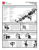
1. Prepare door jamb for hybrid electric strike per the appropriate
template detail (see pages 4-6). Be sure to allow enough room
behind the strike in the cutout to avoid pinching any wires.
2. Drill a 3/8” hole for the door position switch per the appropriate
template detail (see pages 4-6). Note that the door position switch
may be positioned as desired, within limits of its 10” connector. If
necessary (e.g. wood frames), drill a channel from the door position
switch to hybrid electric strike to accommodate the 10“ cable.
Next, drill a matching 3/8” hole in the door and install the press-fit
magnet so that it will contact with the door position switch.
3. If applicable (e.g. aluminum frames),install mounting tabs (sold
separately as P/N 152), using #10-32 screws.
4.Verify that the strike is in the correct mode of operation. This unit
ships in fail secure mode. If you need to convert to fail safe,
see page 7.
5. Check that the wires running from the host control panel and/or
power supply are correct for the components and distance (see
Wiring Diagram on page 2 and Wire Gauge Diagram below).
Connect the three pigtails provided (8 pin, white 2 pin and black 2
pin) to these wires and apply grease as needed. connect the three
pigtails to the hybrid electric strike. Note: It doesn’t matter which
2 pin connector is used. When power is connected, the hybrid
electric strike will automatically run the initialization/self test
described in step 14.
6. Connect and mount the door position switch, routing its 10”
cable from the door position switch to the hybrid electric strike.
7. Plug the loose end of the door position switch cable into its 2
pin connector on the bottom of the hybrid electric strike and apply
grease as needed.
8. Connect the wire bundle on the side of the hybrid electric strike
to the pigtails/wire back to the host control panel. Check any
pertinent information from the access control system installation
guide or manual.
Prepare Frame
9. Attach the faceplate to the hybrid electric strike, using the #8-32
screws provided.
10. Install the trim enhancer on the hybrid electric strike (if needed
to cover any extra space).
11. Install the hybrid electric strike in jamb cutout, using #12-24
screws provided (or wood screws where necessary).
12. If needed, see page 8 to make horizontal adjustments in frame
(RF5210 only).
13. If applicable, tighten the #10-32 screws holding the mounting
tabs.
Finish Installing
14. When power is supplied to the hybrid electric strike, the LED will
flash green three times, while the beeper simultaneously beeps. The
LED will then turn red. This sequence indicates that the micro-
controller is operating properly.
15. Present a Proximity ID card to the reader. The LED will turn green,
while the beeper beeps once. This indicates that the card was read
successfully.
16. Simultaneously, the keeper will click open. This indicates that
communication between the host and the hybrid electric strike is
operational.
17. For further testing of communication with the host, consult the
manual for the host control panel or the site’s system administrator.
Testing and Operation
Connect Components and Wiring
Wire Gauge Diagram
Max. One-way Distance Voltage Drop/100’ Recommended AWG
800’
500’
300’
200’
120’
100’ or less
12VDC @ 240 mA
0.15
0.24
0.38
0.61
0.97
1.53
12 Gauge
14 Gauge
16 Gauge
18 Gauge
20 Gauge
22 Gauge
3
CAUTION! Before connecting any device at the installation site, verify that there is 12VDC input voltage using a multimeter.
Many power supplies and low voltage transformers operate at higher levels than listed. Any input voltage outside the electrical
specifications outlined on page 1 may cause severe damage to the unit and will void the warranty. Also note that a linear
power supply is recommended. Finally, this product contains electrostatic sensitive components. We recommend proper
grounding techniques be observed during installation.
Summary of Contents for Assa Abloy RF5010
Page 2: ......