background image

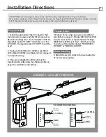
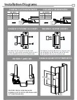
DIAGRAM 3: LATCHBOLT MONITOR

3

Installation Diagrams

DIAGRAM 7: JAMB VIEW

The 4500 is the first strike designed for 

installation in 2” UL 10C fire rated frames with

1/2” drywall penetration

[123.83]

4-7/8”

[79.38]

3-5/8”

[31.8]

1-1/4”

[24.4]

1”

1/2”

LBM WIRING

White

Orange

Normally Open

Green

Normally Closed

Common

DIAGRAM 4: STRIKE MONITOR

DIAGRAM 3: LATCHBOLT MONITOR

Blue

Normally Open

Yellow

Normally Closed

DIAGRAM 3: LATCHBOLT MONITOR

The filler tab for Cylindrical locksets fits 

centered  in the strike opening and is secured 

by the deadlatch tab screws as illustrated

The Mortise lock deadlatch tab is aligned with

the deadlatch on the lockset and secured by 

the deadlatch tab screws as illustrated

DIAGRAM 5: CYLINDRICAL LOCKSETS

DIAGRAM 6: MORTISE LOCKSETS

DIAGRAM 8: JAMB CUTOUT DIMENSIONS

LBSM WIRING

Brown

Blue

Normally Open

Yellow

Normally Closed

Common

Brown

Blue

Yellow

White

Orange

Green

Summary of Contents for 4500 Series

Page 1: ...AC 24VAC INTERMITTENT DUTY Resistance in Ohms Amps Solenoids are rated at 10 indicated value 10 max duty cycle 2 min max on time 200 feet or less 200 300 feet 300 400 feet 18 gauge 16 gauge 14 gauge 18 gauge 18 gauge 16 gauge 3 7 5 2 4 1 ASSA ABLOY the global leader in door opening solutions Product Components Trim Enhancer with screws 12 24 Volt Pigtails 12 24 Mounting Screws 1 2 4500 Electric St...

Page 2: ... must be installed in the strike body See Diagram 5 6 on page 3 for installation instructions Prepare Strike should use the template labeled CYLINDRICAL LOCKSET or MORTISE LOCKSET 5 Attach the electric strike to the jamb using the 12 24 screws provided Finish Installing CAUTION Before connecting any device at the installation site verify input voltage using a multimeter Many power supplies and low...

Page 3: ...BOLT MONITOR Blue Normally Open Yellow Normally Closed DIAGRAM 3 LATCHBOLT MONITOR The filler tab for Cylindrical locksets fits centered in the strike opening and is secured by the deadlatch tab screws as illustrated The Mortise lock deadlatch tab is aligned with the deadlatch on the lockset and secured by the deadlatch tab screws as illustrated DIAGRAM 5 CYLINDRICAL LOCKSETS DIAGRAM 6 MORTISE LOC...

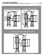
Page 4: ...Lock Strike 5 8 1 1 4 4 7 8 4 1 8 3 5 8 C L C L Strike Prep C L Strike Lock Strike Prep C L 3 8 Vertical Centerline 8 4 C L Mortise Lockset C L Strike Lock Strike Prep C L Vertical Centerline C L Mortise Lockset C L 57 15 28 57 44 45 31 8 31 8 15 88 123 83 104 77 79 38 4 7 8 123 83 4 1 8 104 77 3 5 8 79 38 5 8 15 88 1 1 4 31 8 9 53 1 1 4 31 8 1 3 4 44 45 203 2 101 6 3 5 8 79 38 5 8 15 88 4 7 8 123...

Reviews: