


I n s t a l l a t i o n , O p e r a t i o n , & M a i n t e n a n c e M a n u a l
12
www.herrmidifier-hvac.com
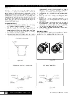
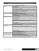
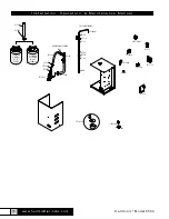
cylinder. Be sure that the o-ring is in place on the cylinder
fill/drain port prior to installation. (See Figure 12A.) New
o-ring is included with each replacement cylinder.
5. Clean and check both the fill and drain valves while servicing
the unit.
6. Check the strainer. If it is dirty or restricting the water,
replace it.
7. Install cylinder in unit by pushing downward with a slight
twisting motion, while ensuring proper orientation of cylinder
within cabinet.
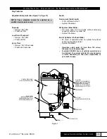
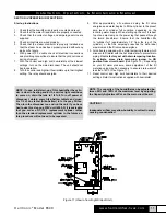
8. Reconnect electrode power wires (#32 & #33) and cylinder
full electrode wire (#26). Make sure that all electrical
connections are securely tightened. (See Figures 12B,
12C, and 12D.) Replace cover and four screws.
9. Follow cold start-up instructions on page 11. Monitor amp
draw for several cycles.
Extended Shutdown
Always drain cylinder completely if unit will be off for an extended
period of time. This will preserve the life of the cylinder.
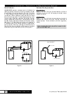
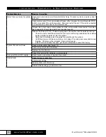
Figure 12B
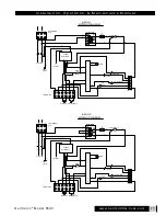
Figure 12D
Herrtronic
®
Model 6500
CYLINDER FULL
ELECTRODE
WIRE #26
POWER
WIRE #33
POWER
WIRE #32
115V UNIT
CYLINDER FULL
ELECTRODE
WIRE #26
POWER
WIRE #33
POWER
WIRE #32
230V UNIT
A
C
E
D
E
C
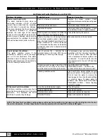
Maintenance
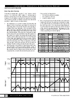
To maintain output, the water level in the cylinder will slowly
move upwards, exposing new electrode to the water as the
electrodes become coated with minerals. Eventually, all of the
usable electrode surfaces will be coated and the cylinder will
be full of water. At this point, the output capacity will begin to
drop and the red “fault” light will come on (fast blink). The unit
will shutdown. This indicates the need to change the cylinder,
typically after 500-2000 hours of operation, depending on the
quality of the fill water supply.
To replace the cylinder
1. Remove cover and four screws while being careful of wiring.
Drain cylinder completely using the drain switch.
2. Turn off power to the unit at the external disconnect.
Disconnect electrode power wires (#32 & #33) and cylinder
full electrode wire (#26) from the cylinder. These connections
are 1/4” quick connects. (See Figures 12B, 12C, and 12D.)
3. Disconnect 1” hose at top of cylinder.
4.
Remove cylinder, clean out the drain cup and insert the new
Figure 12A
Figure 12C


