background image

54

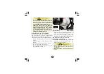
(2) Oil strainer screen cap

2

(3) Spring (4) Oil strainer screen (5) O-ring

1

(1) Drain bolt

Remove the oil strainer screen cap (2). 

The spring (3) and oil strainer screen (4) 

will come out when the oil strainer screen 

cap is removed.

Clean the oil strainer screen.

Check that the oil strainer screen, sealing 

rubber  and  cap  O-ring  (5)  are  in  good 

condition.

CAUTION

!

!

Engine oil quality is the chief factor affecting 

engine service life. Replace and top-up the 

engine oil as specified in the maintenance 

schedule (pages 47).

When  running  in  very  dusty  conditions,  oil 

changes should be performed more frequently 

than specified in the maintenance schedule.

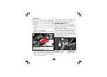
Install the oil strainer screen, spring and oil 

strainer screen cap. Install the drain plug 

with new sealing washer.

At draining: 0.70 litre

Fill crankcase with the recommended grade 

of oil:

Install the oil level dipstick with new O-ring.

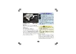
Start  the  engine  and  let  it  idle  for  2-3 

minutes. Stop the engine and ensure that the 

oil level is at the upper level mark on the oil 

level dipstick with the vehicle upright on flat 

level surface. Ensure there are no oil leaks.

At engine disassembly: 0.80 litre

3

4

5

Summary of Contents for PLEASURE+

Page 1: ... Hero MotoCorp are committed to demonstrate excellence in our environment performance on a continual basis as an intrinsic element of our corporate philosophy To achieve this we commit ourselves to continue product innovations to improve environment compatibility comply with all applicable environment legislation and strengthen the green supplychain YourAuthorisedDistributorandDealer s oftheDistri...

Page 2: ...T THE TIME OF ITS PRINTING APPROVAL AND THE ACCURACY OR CORRECTNESSOFTHESAMEISNOTUNDERTAKENORGUARANTEED Hero MotoCorp Ltd RESERVES THE RIGHT TO MAKE CHANGES IN ITS CONTENTS AT ANY TIME WITHOUT NOTICE AND OR INCURRING ANY OBLIGATION WHATSOEVER NO ONE IS ALLOWED TO REPRODUCE ANY PART OF THIS PUBLICATION WITHOUT OBTAINING PRIOR WRITTEN PERMISSIONFROM Hero MotoCorp Ltd NOTE ...

Page 3: ...T 10 Rear view mirror 33 Floor side cover 32 Front upper cover 31 Rear grip 31 BODY PARTS REMOVAL 28 Center compartment 28 Body cover Center cover 30 SERVICE RECORD SHEET OWNERSHIP RECORD AND DATA JOBS APPLICABLE TO PERIODIC SERVICES SERVICE ADVICE SHEET HERO GENUINE PARTS SAFETY PRECAUTIONS 46 TOOL KIT 43 MAINTENANCE 45 AIR CLEANER ELEMENT 50 AIR CLEANER DRAIN TUBE CLEANING 51 MAINTENANCE SCHEDUL...

Page 4: ......

Page 5: ...5 Engine JF33AD Variants JFW08 JF33AD VIN MBLJFW08 1 Duringregistrationofthevehicle 2 Fordealingwithlegal insurancedepartments VINandEngineNo mayberequired Sheet metal wheel Integrated braking Cast wheel Integrated braking 1 MBL JFW08 Manufacturer code Vehicle Description Model Year Check Digit Engine No JF33AD JF33AD Engine Description Year of Manufacturing Assembly Plant Plant Code Month of Manu...

Page 6: ...ssembly 0 10 litre at draining 4 8 litres 6 0 kW 8 BHP 7500 rpm 8 70 N m 5500 rpm 50 0x56 5 mm 9 5 1 110 9 cc Champion PRZ 9 HC Federal Mogul Capacities Engine Spark plug gap Valve clearance Idle speed Front suspension Rear suspension Caster angle 0 6 0 7 mm 0 14 0 02 mm 0 14 0 02 mm 1700 200 rpm 27 30 Intake cold Exhaust cold Chassis and suspension Spark plug Chassis type High rigidity under bone...

Page 7: ...ogen bulb MFR 12V 5W 21W MFR 12V 10W x 4 nos MFR Clear lens Amber bulb 12V 1 7Wx2 nos Turn signal indicator 12V 3 0Wx2 nos Hi beam indicator Side stand indicator Fuse 12V 1 7W 12V 1 7W 15A 10A Circuit fuse 15A 10A Spare fuse MF stands for Maintenance Free MFR stands for Multi Focal Reflector Internal expanding shoe type Dia 130 mm Integrated braking system Clutch system Dry automatic centrifugal c...

Page 8: ...also recommend that you wear eye protection sturdy boots gloves and other protective gear page6 Take time to learn practice your vehicle Some drivers do not see vehicles because they are not looking for them To make yourself more visible wear bright reflective clothing position yourself so that others can see you signal before turning or changing lanes and usehornwhichwill helpotherstonoticeyou Ri...

Page 9: ... possible wearing proper gear can reduce the chance of injurywhenyouride Ifyouareinvolvedinacrash Personal safety is your first priority If you or anyone else has been injured take time to assess the severity of the injuries and whether itissafetocontinueriding Callforemergency assistance if needed Also follow applicable laws and regulations if another person or vehicleisinvolvedinthecrash If you ...

Page 10: ...PROTECTIVE APPAREL Always wear HELMET Wear bright or reflective clothing Wear a face shield or goggles Wear gloves Shoes should be close fitting low heels and offer ankle protection 6 ...

Page 11: ... modifications Rearluggagehook 3 0kg Putting too much weight in individual storage compartments can also affect stability and handling So be sure to stay within the limits givenbelow Maximumweight Centercompartment 10kg InnerrackorFrontbox 1 5kg Includes the weight of the rider pillion all cargoandallaccessories Load limits Followingaretheloadlimitsforyourvehicle Maximumweightcapacity 130 kg 2 3 1...

Page 12: ...d alwaysfollowtheseguidelines Be sure electrical equipment does not exceed the vehicle s electrical system capacity page 3 A blown fuse can cause lossoflights Modifications Removing or modifying your lamps muffler emission control system or other equipment can also make your vehicle not meeting the emissionstandards Do not pull a trailer or sidecar with your vehicle This vehicle is not designed fo...

Page 13: ...tween40 50km hr Always wear a helmet with chinstrap securely fastened and insist on a helmet for your pillion rider Helmet should conform as per safety standards applicable in your country ake care T of loose hanging clothes while solo pillionriding Get your vehicle serviced regularly by the AuthorisedDistributor Dealer Do not attach large or heavy items to the handlebars Never take your hands off...

Page 14: ...rmance Regular servicing Get your vehicle serviced at an Authorised service station as per the serviceschedule foranoptimumperformanceandkeeptheemissionlevelundercheck Thefollowingtipsshallensureahealthyvehicle healthyenvironment andahealthyyou Genuine spares Always insist on Hero MotoCorp genuine parts as spurious or incompatible spares and accessories can upset or deteriorate your vehicle s runn...

Page 15: ...mmer switch 10 Fuel gauge 11 Side stand indicator 12 Turn signal indicator 13 High beam indicator 14 Front brake lever 17 Ignition switch with steering lock 15 Throttle grip 16 Starter switch 18 USB charger Accessories and features shown may not be part of standard fitment TOP VIEW VEHICLE VIEWS 14 15 16 17 5 4 2 3 1 12 9 7 8 13 11 10 11 18 6 ...

Page 16: ...t be part of standard fitment 7 1 1 Side stand switch 2 Side stand 3 Main stand 4 Kick starter pedal 5 Pillion step 6 Rear turn signal lamp 7 Tail stop lamp 8 Rear grip 10 Luggage hook 9 Boot lamp inside 11 Headlamp LEFT SIDE VIEW 12 9 2 3 4 5 11 ...

Page 17: ...llion step 4 Inner rack or Front box 5 Front reflex reflector 6 Front turn signal lamp 7 Center compartment inside 8 Document compartment inside RIGHT SIDE VIEW 6 3 4 2 1 7 Accessories and features shown may not be part of standard fitment 13 8 5 ...

Page 18: ... Light glows when headlamp is in high beam Speedometer Indicates driving speed Turn signal indicator Flashes when turn signal switch is operated Whenthefuelgaugeneedle 1 entersthered band 2 fuel will be low and you should refill thetankassoonaspossible FUELGAUGE 1 Fuel gauge needle 2 Red band 6 Fuel gauge Indicatesapproximatefuelquantity Side stand indicator Light glows when the vehicle is parked ...

Page 19: ... on integrated brake arm 2 Integrated brake lever 3 Free play 10 20 mm 2 3 Turnthefirstadjusternut 5 tillyoucannot turnitbyhand FREEPLAY 10 20mm Push the integrated brake arm 4 by hand inthedirectionasshown The distance the front brake lever 1 and integratedbrakelever 2 movesbeforeeach brake starts to engage is called free play 3 Measured at the tip of brake levers free play shouldbemaintainedat10...

Page 20: ...ment FREE PLAY 10 20 mm Make free play adjustment by turning the adjusternut 1 inthebrakearm 2 REARBRAKE Check the free play of integrated brake lever If the free play is more than 20 mm further turn the adjuster nut to obtain desired free play ii i 2 1 Lefthandfrontbrakecable B on I side Turn the second adjuster nut 6 until a gap is created between joint 7 and the slot on thefirstsideinintegrated...

Page 21: ...se and damage caused by misuse is not covered under Hero MotoCorp warrantypolicy NOTE Apply the brake several times and check for free wheel rotation after the brake lever is released 2 NOTE Tightening position of the fuel filler cap can change upto 20 clockwise from the standard position based on the variable tighteningeffortsdonebydifferentusers Do not overfill the tank There should be no fuel 3...

Page 22: ...pe and size in good condition with adequate tread and correctly inflated for the load you are carrying The following pages give more detailed information on how and when to check the air pressure how to inspect your tyres for damage and what to do when your tyres need to be repaired or replaced WARNING Follow all instructions in this owner s manual regarding tyres inflation and maintenance Riding ...

Page 23: ... if they are punctured However because leakage is often very slow you should look closely for punctures whenever a tyre is not fullyinflated Always check air pressure when your tyres are cold when the vehicle has been parked for at least three hours If you check air pressure whenyourtyresare warm whenthevehicle has been ridden for even a few km the readings will be higher than if the tyres were co...

Page 24: ...rdrotationofwheel If a tyre is punctured or damaged you should replace it not repair it As mentioned below a tyre that is repaired either temporarily or permanently will have lower speed and performancelimitsthananewtyre Tyre repair Unidirectional tyres You should not exceed 70 km hour for the 1st 24 hours or 105 km hour at any time thereafter In addition you may not be able to safely carry as muc...

Page 25: ... your vehicle and provide the best combination of handling braking durabilityandcomfort The tyres that were installed on your vehicle were designed to match the performance Front 90 100x10 53J Tubelesstyre Rear 90 100x10 53J Tubelesstyre Therecommendedtyreforyourvehicleare NOTE For repair and replacement of tyre it is advised tovisityourAuthorisedDistributor Dealer Importantsafetyreminders Donotin...

Page 26: ...ion switch 1 3 LOCK Position The engine can be started Turn signal indicators Horn Tail Stop lamp and Fuel gaugewillbefunctional Steering can be locked Engine cannot be started and no electrical systemwillbefunctional LOCK Key position Function Key cannot be removed Key can be removed Key can be removed Key removal 2 ON Position OFF Position Lock Open ON OFF ...

Page 27: ...sh insideasdirectedontheswitch 23 1 Dimmer switch 2 Turn signal switch 3 Horn switch 1 2 3 Righthandlebarcontrols The electric starter switch 1 is next to the throttlegrip 1 Electricstarterswitch Whenthestarterelectricswitchispressed the starter motor cranks the engine with the front orintegratedbrakeleverapplied 1 Electric starter switch FEATURES a Steering lock Tolockthesteering turnthehandlebar...

Page 28: ... The seat will release from its latch 2 Remove the helmet from the holder and closetheseat Opentheseat Attach Hook the helmet strap or ring to thehelmetholderandclosetheseat Toreleasethehelmetfromtheholder Opentheseat 1 Helmet holder 2 Helmet WARNING Use the helmet holder only while parked Do notridewithahelmetsecuredbytheholder Riding with a helmet attached to the holder can interfere with the ob...

Page 29: ...oes off automatically when the seatisclosed 1 Center compartment 2 Document compartment d c Center ompartment The center compartment 1 is below the seat For opening and closing the seat lock see page24 MAXIMUM WEIGHTLIMIT 10kg 1 2 Do not direct pressurised water spray against the center compartment as water may enter intothecompartment The owner s manual other documents tool kitcanbestoredinit e D...

Page 30: ...Charge your device only when the engine is operational while riding Charging the USB device when the engine is OFF would lead toearlydischargeofbattery Do not leave the USB device and USB cable intheinnerrackwhenthevehicleisparked NOTE Anypersonalbelongingshavetoberemoved beforewaterwashingtoavoiddamage Always keep the USB port cap closed after use to prevent dust or water entry during rains water...

Page 31: ...nables the side stand indicator lamp to glow on the The luggage hook 1 is located below the frontendoftheseat MAXIMUMWEIGHTLIMIT 3 0kg h h Luggage ook 1 1 Luggage hook MAXIMUMWEIGHTLIMIT 1 5kg i InnerrackorFrontbox The inner is provided to carry some rack 1 items documents etc Never exceed the maximum weight limit of the inner otherwise handling and stability rack maybeseverelyaffected WARNING Do ...

Page 32: ... the side stand for proper function and the spring 3 for damage or loss of tension and the side stand assembly for free movement If the side stand indicator 1 does not operate as described in above steps please visityour AuthorisedDistributor Dealer 2 2 Side stand switch 3 Side stand spring CAUTION Ensure that adequate care should be taken whilecleaningthesidestandswitch 3 l Pillionfootrest Move t...

Page 33: ...e vehicle with the center compartment removed 7 Boot lamp connector 7 Removecentercompartment 8 5 Screws 6 Bolts 5 6 1 Fuel filler cap 2 Bolts 3 Fuel tank cover 2 3 Removethedrainpipe 4 Installthefuelfillercap page17 Remove the center compartment screw 5 andbolts 6 4 Drain pipe 1 4 1 ...

Page 34: ... 3 Ÿ Similarlyremoveleftsidebodycover Ÿ Remove right side body cover 4 by dislodgingthetabs 4 30 Installation b Bodycover Installationisinthereverseorderofremoval Remove the screws 1 and rear center cover 2 bydislodgingthetabs Removal Removecentercompartment page28 8 Center compartment 8 2 1 Screws 2 Rear center cover 1 Remove the screws 3 from both left and rightsidebodycovers ...

Page 35: ...ntheseat page24 Removethereargrip 2 Installation is in the reverse order of removal Ÿ Removethecentercover 2 Installation Removethefueltankcover page28 Removal d Rear grip Removethebolts 1 1 Bolts 2 Rear grip 1 2 Remove screws 1 from the front end of thevehicle e Front upper cover Installation is in the reverse order of removal Installation Removal ...

Page 36: ...odge the tabs 3 slide the floor side covers to the rear side and pullout the floor sidecover 1 1 Screws 2 Floor side cover 2 3 Tabs 3 3 3 Left turn signal lamp connector 4 Right turn signal lamp connector 3 Remove the front upper cover 5 by dislodgingthetabs 4 5 Front upper cover 5 Installation Installationisinthereverseorderofremoval ...

Page 37: ...rews 3 on rear handlebar cover 4 Loosen the rear view mirror 3 and removeit Loosen the lock nut 2 until it will no longerturn Removal g Rearviewmirror Slidethedustcoverup 1 1 Dust cover 2 Lock nut 3 Rear view mirror 1 3 2 NOTE To remove the left floor side cover open the sidestand Ensure that the floor side cover tabs are seatedproperly Installation Installationisinthereverseorderofremoval Loosen ...

Page 38: ...awall Turntheignitionto ON position Loosen the bolt 1 and move the headlamp up A or down B for correct focus 1 Bolt A Up B Down WARNING An improperly adjusted headlamp may blind oncoming driver or it may fail to light the road forsafedistance 1 Disconnect the headlamp connector 5 andremovetheheadlampcase Pull the headlamp case slightly up carefully releasethetabsfromtheslots 4 3 Screws 4 Rear hand...

Page 39: ...ls that are still with them STARTINGTHEENGINE ANTI THEFTTIPS Park your vehicle in a locked garage wheneverpossible NAME _______________________________ WARNING Improper maintenance or failing to correct a problem before riding can cause a crash in whichyoucanbeseriouslyinjured Always perform a pre ride inspection beforeeveryrideandcorrectifanyproblem Fuel level Fill fuel tank when necessary page17...

Page 40: ...r closed Even with the door open run the engine only long enough to moveyourvehicleoutofthegarage Do not use the electric starter for more than 5 seconds at a time Release the starter switch for approximately 10 seconds before pressingitagain CAUTION Do not attempt to start the engine and run the vehicle without a battery This may lead to electricalandelectroniccomponentsfailure Lock the rear whee...

Page 41: ...movingthevehicleoffthemainstand With the throttle closed operate the kick starterwitharapidandcontinuousmotion Ensure your vehicle s future reliability and performance by paying extra attention to how yourideduringthefirst500km Donotusethebystarter With the throttle closed operate the kick starterwitharapidandcontinuousmotion Usekickstarter RIDING RUNNING IN Warmengine During this period avoid ful...

Page 42: ... 1 Mount the vehicle from the left side keeping at least one foot on the ground tosteadythevehicle Stand on the left side of the vehicle and push it forward off the main stand gripping below the seat using the right handasshown I N E G T R A T E D B R A K I N G S Y S T E M Unlock the integrated brake by further pressingtheintegratedbrakelever 1 soas to release the parking lever 2 from the lock The...

Page 43: ...n may cause the wheels to lock reducing control over the vehicle 2 Front brake 3 Integrated brake km 100 km h 20 40 60 80 000030 F E 0 3 2 CLOSE 1 Do not open and close throttle rapidly as it will make the vehicle to move forward suddenly causing possible loss of control andlossoffueleconomy To accelerate open the throttle 1 gradually the vehicle will move forward Do not accelerate with the brakes...

Page 44: ...0 2 When approaching a corner or turn close the throttle 1 fully and slow down the vehicle by applying integrated brake 2 After completing the turn open the throttle gradually to accelerate the vehicle 1 1 Throttle 2 Integrated brake CLOSE ...

Page 45: ...hen descending a steep gradient close throttle 1 fully and apply integrated brake 2 toslowdownthevehicle Avoid continuous use of the brakes which may result in overheating and reduction of brakingefficiency 2 Integrated brake 1 Throttle 1 CLOSE ...

Page 46: ...e surfaces the ability to manoeuvre and stopwillbereduced After stopping the vehicle turn the ignitionswitchto OFF position Use the main stand to support the vehicle whileparked lockandremovethekey Lockthesteeringtopreventtheft NOTE If you must park on a slight incline aim the front of the vehicle uphill to reduce the possibility of rolling off the main stand or overturing Park the vehicle on firm...

Page 47: ...y with water to removeloosedirt Clean the plastic parts using a cloth or sponge dampened with a solution of mild Cleanthevehiclewithaspongeor softcloth usingwater Avoid directing water to meter console muffleroutletsandelectricalparts If your vehicle is still warm from recent operation give time for the engine and exhaust systemtocooldown We recommend avoiding the use of high pressurewaterspray Cl...

Page 48: ...headlamp lens will disappear gradually by lightingtheheadlampinhighbeam Take care to keep brake fluid or chemical solvents off the vehicle They will damage theplasticandpaintedsurfaces Test the brakes before riding the vehicle Several applications may be necessary to restorenormalbrakingperformance Braking efficiency may be temporarily impaired immediately after washing the vehicle Anticipate long...

Page 49: ...section includes instructions on some important maintenance tasks You can perform some of these tasks with the tools provided ifyouhavebasicmechanicalskills You will come across some of the most important safety precautions in the following pagesofthismanual To help you to take proper care for your vehicle the following pages include a maintenance schedule and a maintenance record for regular sche...

Page 50: ...d avoid the possibility of someone being injuredfromcontactingthewheel To prevent the vehicle from falling over park it on a firm level surface on the main stand Read the instructions before you begin and make sure you have the tools and skills required Injury from moving parts Carbon monoxide poisoning from engineexhaust Make sure the engine is turned OFF before you begin any maintenance or repai...

Page 51: ...ingmaintenanceschedulespecifiesallmaintenancerequiredtokeepyourvehicleinpeakoperating condition Maintenance work should be performed in accordance with standards and specifications of Hero MotoCorp by properly trained and equipped technicians Your meets all of Authorised Distributor Dealer theserequirements In the interest of safety we recommend that these jobs are carried out only by your Authori...

Page 52: ...ext 90 Next 90 Next 90 1st 60 Next 90 I C Drain Crankcase Breather Tube I C I C I C Note 4 I C I C Engine Oil R T R R T T R C Secondary Air Cleaner Element C C C C C C L C L C L C L C L C L Brake System I I I Final Drive Oil R Engine Idle Speed Carburetor Secondary Air Injection System Air Cleaner Element Note 3 Note 2 Note 5 th 6 Next 90 th 7 th 8 th 9 th 10 th 11 Next 90 Next 90 Next 90 Next 90 ...

Page 53: ...s Rear Suspension Front Suspension Oil Belt Case Kick Starter Driven Gear Drive Belt L L L L L L L L L L L L I C I C I C I C I C I C Main Stand Side Stand Switch Side Stand Wheel Bearings Brake Shoe Wear th 6 Next 90 th 7 th 8 th 9 th 10 th 11 Next 90 Next 90 Next 90 Next 90 Next 90 15000 15500 18000 18500 21000 21500 24000 24500 27000 27500 30000 30500 I I I I I I I I I I I I I I I I I I I I I I ...

Page 54: ...Remove the air cleaner cover 1 by removingthescrews 2 leftside page30 Removethe bodycover Inspect the air cleaner element for any dust ordirtaccumulation Replace the air cleaner element if found choked Remove the air cleaner assembly 3 from housing 4 3 Air cleaner assembly 4 Air cleaner housing 3 Clean the air cleaner housing 4 using a shoptowel Installtheaircleanerassembly new incase ofreplacemen...

Page 55: ... page30 Installthe Installtheaircleanercover Replace air cleaner element once in every 15000 km or early replacement may be requiredwhenridingindustyareas At 12000 km inspect if air cleaner element is choked If found choked replace the air cleanerelementtokeeptheenginehealthy NOTE 1 Screw 2 Tabs 3 Secondary air filter cover 1 3 2 4 Secondary air cleaner element 4 Refertothesafetyprecautions page48...

Page 56: ... throttle grip THROTTLE OPERATION Cable inspection from the fully open to the fully closed position Check at full left and full right steering positions Inspect the condition of the throttle cable from the throttle grip down to the 2 Boot 3 Lock nut 4 Adjuster A Decrease free play B Increase free play 3 A B 4 2 5 Boot 6 Lock nut 7 Adjuster A Decrease free play B Increase free play A B 7 6 carburet...

Page 57: ... recommended oil up to the upperlevelmark Donotoverfill Park the vehicle on its main stand on a level surface Start the engine and let it idle for few minutes Remove the oil level dipstick and check if the oil level is between the upper and lower marks Reinstall the oil level dipstick with new O ring Checkforoilleaks Remove the oil level dipstick wipe it clean and reinsert the oil level dipstick w...

Page 58: ...il as specified in the maintenance schedule pages47 When running in very dusty conditions oil changesshouldbeperformedmorefrequently thanspecifiedinthemaintenanceschedule Install the oil strainer screen spring and oil strainer screen cap Install the drain plug withnewsealingwasher Atdraining 0 70litre Fill crankcase with the recommended grade ofoil InstalltheoilleveldipstickwithnewO ring Start the...

Page 59: ...emovetheoillevelcheckbolt 1 The final drive oil should be replaced as per the maintenance schedule Replacement requires mechanical skill It is suggested to get itreplacedby AuthorisedDistributor Dealer Park the vehicle on its main stand on a level surface Remove the drain bolt 2 slowly turn the rearwheelanddraintheoil 1 Check bolt 2 Drain bolt 2 1 Aftertheoiliscompletelydrained installthe oildrain...

Page 60: ...wetfouled plugwithaplugcleaner Check the spark plug gap using a wire type feeler gauge If adjustment is necessary bendthesideelectrode 2 carefully 0 6 0 7 mm 2 Side electrode 2 WARNING The spark plug must be securely tightened An improperly tightened plug can become veryhotandpossiblydamagetheengine Never use a spark plug with an improper heat range Severe engine damage could result Tighten a new ...

Page 61: ...4 Brake panel 2 4 4 1 1 Adjust idle speed by adjusting the throttle stop screw by inserting a suitable screw driver 2 from the opening provided in thefloorpanelasshown Ÿ Idle stop screw is visible from the carburetor maintenance window 3 providedinthecentercompartment 4 Idlespeed 1700 200rpm BRAKESHOEWEAR When the brake is applied an arrow mark 1 on the brake arm 2 moves towards a referencemark 3 ...

Page 62: ...cyto discharge rapidly if any additional electrical accessoriesarefittedonyourvehicle Battery charging NOTE This symbol on the battery means that this product must not be treated as householdwaste This symbol on the battery means the old battery must be returned to your Authorised Distributor Dealer as it mustbetreatedasrecyclablematerial Battery is a Maintenance Free sealed type and can be perman...

Page 63: ...p 2 by removing thebolt 3 Disconnectthe veterminallead 4 from the battery first then disconnect the ve terminallead 5 1 Fuse boxes 2 Battery clamp 3 Bolt 4 ve terminal 5 ve terminal 6 Battery 4 6 Batteryinstallation Spare fuse 4 10A Check the bolts and other fasteners are securedproperly Reinstall in the reverse order of removal Be suretoconnectthe veterminalfirst then the veterminal The fuse hold...

Page 64: ...e the blown fuse in that circuit and have your vehicle checked by your Authorised Distributor Dealer SUSPENSION Check the front forks by locking the front brake and pumping the front fork up and down vigorously The suspension action shouldbesmoothandthereshouldbenooil leakage Check the rear shock absorber by pushing hard downwards on rear grip while the vehicle is not parked on stand The vehicle a...

Page 65: ...installing a new bulb check that the lampoperatesproperly Removethedustcover 2 Releasetheclip 3 fromitsposition Remove the headlamp bulb 4 without turning Install a new bulb in the reverse order of removal Installtheheadlampcase page33 1 Bulb holder 2 Front turn signal bulb Install a new bulb in the reverse order of removal Installthefrontuppercover page31 b Front turn signal bulb Removethefrontup...

Page 66: ...cable Remove the rear turn signal bulb 1 by turningittoanticlockwisedirection Removetherearcentercover page31 Installthereargrip page31 Remove turn signal bulb holder with bulb by turninganticlockwise Install a new tail stop lamp bulb 4 in the reverseorderofremoval Installthetail stoplampunitinthevehicle Installthebodycovers page31 Dismount the tail stop lamp unit from thevehiclebyremovingthebolts...

Page 67: ...atalytic converter contributes to air pollution and can impair your engine s performance that serve as catalyst promoting chemical reactions to convert CO and HC in the exhausttoCO andH O watervapour 2 2 This vehicle is equipped with a catalytic converter inthemuffler Keeptheenginetunedup rearcentercover page31 Installthe CATALYTICCONVERTER Follow these guidelines to protect your vehiclecatalyticc...

Page 68: ... siphon or an equivalent method REMOVINGROADSALT The road may contain salt which was sprayed as an anti freezing agent during winter and theseawaterarethecausesofrust Thisworsenstheeffectofthesalt Spray the inside of the tank with an aerosol rustinhibitingoil If storage lasts more than a month carburetor draining is very important to assureproperperformanceafterstorage Reinstallthefuelfillercapont...

Page 69: ...e has been stored for morethan4months Check the battery voltage and charge the batteryasrequired Installthebattery e Inflate the tyres to their recommended pressures Park the vehicle on blocks to raisebothtyresofftheground Drain any excess aerosol rust inhibiting oil from the fuel tank Fill the fuel tank with freshpetrol Perform all pre ride inspection checks page 34 Test ride the vehicle at low s...

Page 70: ...nsult Authorised Distributor Dealer Check spark plug for fouling Improper electrode gap Replace spark plug adjust Spark plug gap 0 6 0 7 mm Loose contact Check for poorly connected Or loose spark plug wire Secure properly Check fuel in fuel tank Ok Ok Check fuel lines Leakage air lock Refill Rectify No fuel A Fuel System Consult Authorised Distributor Dealer 1 STARTING TROUBLE ENGINE DOES NOT STAR...

Page 71: ...ure connections Consult Authorised Distributor Dealer Consult Authorised Distributor Dealer Spark plug loose in cylinder head Ok Check air cleaner element Ok Ok Check brake binding Improper Adjustment Tighten the spark plug Readjust free play of rear brake lever Loose 3 POOR PICK UP Ok Check tyre inflation pressure Under inflated Correct tyre pressure Consult Authorised Distributor Dealer Replace ...

Page 72: ...ELIVERY CERTIFICATE No IB31A Engine No VIN No Colour Model Key No Allotment No Customer s Name Date of Sale I have been explained by the about correct and safe driving habits dealer warrantytermsandconditions serviceschedulesandmaintenancetips Customer s Copy Hero MotoCorp Ltd C U S T O M E R S C O P Y ...

Page 73: ... of tools for details see below 4 Standard Accessories 5 Battery 6 Tyre Front Rear Make Make Make Sr No Sr No Sr No Thevehiclehasbeendeliveredinfactoryfreshconditionstomysatisfaction I haveunderstoodalltermsandconditionsofwarrantyandshallabidebythem Customer s Address Customer s Signature Customer s Name Authorised Distributor Dealer Name Authorised Distributor Dealer Address ...

Page 74: ...by the about correct and safe driving habits dealer warrantytermsandconditions serviceschedulesandmaintenancetips Hero MotoCorp Ltd VIN No Authorised Distributor Dealer Copy AUTHORISED DISTRIBUTOR DEALER COPY I certify having taken delivery of one Hero MotoCorp PLEASURE Vehiclebearingthefollowingparticulars No IB31A ...

Page 75: ... of tools for details see below 4 Standard Accessories 5 Battery 6 Tyre Front Rear Make Make Make Sr No Sr No Sr No Thevehiclehasbeendeliveredinfactoryfreshconditionstomysatisfaction I haveunderstoodalltermsandconditionsofwarrantyandshallabidebythem Customer s Address Customer s Signature Customer s Name Authorised Distributor Dealer Name Authorised Distributor Dealer Address ...

Page 76: ...mages other parts of clutch like clutch center and outerclutch Higheremissionlevel Leadstoleakageandsmokyexhaust Impropersealing Engineknocking Affectsfuelefficiency Improperairfiltrationresultinginprematureenginefailure Poorengineperformance Gasket Cylinder Head Element Air Cleaner Spark Plug Higher emission level Frequentstallingofengine Poor engine performance Affects fuel efficiency Rider safe...

Page 77: ...eanerelementateveryservice Inspectsecondaryairinjectionsystematevery6000km Testdrivethevehicleifrequiredforreportedtroubles ifany Washthevehicleandblowdrywithairateveryservice Inspectfuellinesateveryservice Inspectthrottlefreeplayandoperation ateveryservice adjustifnecessary Testdrivethevehicleforrepairofproblemsreported Cleanandpolish exceptmattepaintedmodels thevehiclebeforedelivery Inspect stee...

Page 78: ...hicheverisearlier 500 750 3000 3500 6000 6500 9000 9500 15000 15500 12000 12500 18000 18500 21000 21500 24000 24500 I II III IV V VI VII VIII IX 27000 27500 30000 30500 33000 33500 36000 36500 42000 42500 39000 39500 X XI XII XIII XIV XV 45000 45500 XVI 48000 48500 XVII Free Paid Service Km Range Date Km Reading Job Card No Authorised Distributor Dealer Sig Stamp SERVICE RECORD SHEET To be Filled ...

Page 79: ...0 60000 60500 63000 63500 66000 66500 72000 72500 69000 69500 XX XXI XXII XXIII XXIV XXV SERVICE RECORD SHEET To be Filled in by Supervisor Free Paid Service Km Range Date Km Reading Job Card No Authorised Distributor Dealer Sig Stamp Engine Oil Top up Replace ...

Page 80: ...Date Job Card No Kms Advice Authorised Distributor Dealer Sig Stamp Job Card No Completion Dt SERVICE ADVICE SHEET Normal wear and tear components replacement advice ...

Page 81: ...Hero MotoCorp Ltd OWNERSHIP RECORD AND DATA VIN AUTHORISED DISTRIBUTOR DEALER NAME ADDRESS AUTHORISED DISTRIBUTOR DEALER STAMP AND SIGNATURE ...

Reviews: