Hensel EXPERT D 1000, User Manual
The Hensel EXPERT D 1000 User Manual is an essential guide for maximizing the potential of your photography equipment. Download the comprehensive manual for free from manualshive.com to access step-by-step instructions, detailed product features, and valuable tips for capturing breathtaking photographs.
Share
Download


Reviews:
No comments
Related manuals for EXPERT D 1000
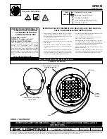
Orion
Brand: B-K lighting Pages: 2

E-SPARK
Brand: Fenix Pages: 5

501978262
Brand: PROF Pages: 42

6060120A
Brand: Ritos Pages: 25

PFMTF50
Brand: Police Force Pages: 4

BSL18UA
Brand: Hitachi Pages: 4

UB 18D
Brand: Hitachi Pages: 8

UB 10DL
Brand: Hitachi Pages: 2

UB 18DAL
Brand: Hitachi Pages: 2

UB18DAL
Brand: Hitachi Pages: 4

FL dual sensor F70/400
Brand: Beghelli Pages: 2

Nova 220
Brand: Uwatec Pages: 36

SX 450IC-2000+E
Brand: WISKA Pages: 28

DT-826437
Brand: RAW Pages: 8

LED084
Brand: Sealey Pages: 3

Robin BMFL WashBeam
Brand: Robe Pages: 60

NL 300
Brand: Olympia Pages: 26

ION
Brand: Dapper Design Pages: 3


