
Important: Always read and follow instructions.
Calibration
Machine Calibration
1.
Enter the MACHINE CALIBRATION mode.
2.
Enter the D dimension (include decimal point,
example: 16.0 for a 16-inch wheel). Press ENTER.
3.
Lower the hood and press SPIN.
4.
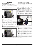
After spin, raise the hood. Attach 4-ounce calibra-
tion weight to the outside flange at top-dead-center.
Figure 40 - Calibration Weight On Outside Flange At Top-Dead-
Center
5.
Lower the hood and press SPIN
Important:
It is critical that the inner weight be placed
accurately to achieve proper calibration. If the calibration
weight is not moved from the outside flange directly
across to the inside flange, an inner weight placement
error will occur. To correct, follow the balancer instruc-
tions.
6.
After spin, raise the hood. Move the 4-ounce cali-
bration weight directly across and attach it on the inside
flange at top-dead-center (12 o’clock position).
Figure 41 - Calibration Weight Moved (Directly Across) To
Inside Flange
7.
Lower the hood and press SPIN.
Note:
Rotate laser dot toward inner flange.
8.
After spin, raise the hood. Rotate wheel to line up/
center of 4-ounce calibration weight with laser dot. Hold
position while pressing NEXT.
9.
Press NEXT; then press EXIT.
Note:
On control panel models complete the machine
calibration procedure. Then press and hold the SHIFT
key and press 3 to access the CAL ARM mode.
10.
Bring the cone edge of the arm precisely to the
outer edge of the faceplate and hold it there (through
step 12) while pressing the NEXT. (If necessary to reach
the faceplate accurately, loosen the calibration wheel
temporarily.)
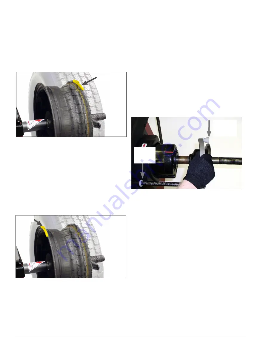
11.
With arm cone still at the edge of the faceplate,
enter the A dimension (include decimal point) read off
the arm gauge; see figure 41. Press ENTER.
Figure 42 - While Holding Arm Cone at Faceplate Edge,
Enter A
12.
Move arm to its home position and press NEXT.
13.
Move arm to clip-on weight location on rim
flange and hold it there (through step 16). Wait for volt-
age reading to stabilize, then press NEXT.
14.
With arm still at clip-on weight location, enter
the D dimension (16.0 for a 16-inch wheel) that is the
diameter of the tire. Press NEXT.
15.
While still holding the arm at the wheel’s clip-on
weight location, enter the A dimension (include decimal
point) read off the arm gauge. Press ENTER
16.
Return the arm to home position; calibration is
complete. Press EXIT. Press STOP & EXIT to go back to
the main screen.
Hold Arm
Cone Edge
At Edge Of
Faceplate
Enter A
Value
Shown On
Arm Gauge
Weight
Weight


