

ADJUSTING AND TUNING YOUR VEHICLE
GENERAL CARE AND MAINTENANCE...
12
General Care:
• Always use clean, dry cloth or soft bristle brush to clean your equipment.
• Never use chemical cleansers to avoid damage to the sensitive electronics and plastics.
Maintenance:
We want you to enjoy your product to its fullest potential. For this to happen it is important to keep your product clean and properly
maintained. Lack of cleaning and maintenance can cause component failure. For best and continued performance from your product
it is recommended to briefly inspect your product for damage every few runs. Typically, a good time to do this is when changing the
battery or while it is charging. If a problem is discovered, stop use immediately and perform repairs or seek assistance. Continued
use of failed components can cause more unnecessary damage to your product. Always remember to use genuine replacement
parts from your local hobby dealer. Below is a list of items for inspection. Inspection should not be limited to this list; if you notice
any problem, listed or not, it is recommended to give it proper attention.
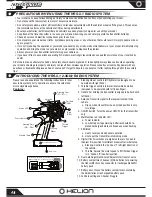
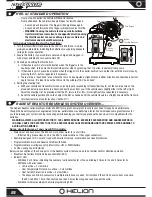
1. Electronics: Although the ESC and servo included in your vehicle are waterproof the receiver is not, however it is contained in a
water resistant box. It is recommended that you avoid submersion of the vehicle however light running in puddles and light rain
should not be damaging. If you plan to run for extended periods of time in light or heavy rain It is recommended to secure the
receiver in an additional waterproof membrane. Since the Helion HRS-3.1 receiver is a micro size receiver, fitting it into a balloon
is fairly easy. Simply insert the receiver with connected wiring into a balloon and secure the balloon around the wires with an
additional rubber band as close to the receiver as possible, allowing the most exposure of the antenna as possible.
2. Antenna: To achieve full operating range with your radio system, it is critical that the receiver antenna be installed properly and
undamaged.
a. Inspect any exposed antenna for cuts or abrasions.
b. Ensure there are no kinks in the antenna or antenna tube.
c. Never fold the end of the antenna over the tube, this will reduce the range and damage the antenna.
d. Ensure the antenna is not being pinched by the set screw that holds the antenna tube in place.
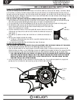
3. Gears: Periodically remove the gear cover to clearly inspect the gears and ensure there is no debris in the gear compartment.
a. Proper gear mesh setting is crucial for proper operation and life of gears in your product. It is important to have the pinion
gear (attached to motor) as close to the spur gear (attached to drive shaft) as possible yet while providing a minimal amount
of backlash. Backlash is the rotation one gear has to make before contacting the other. Having the gear mesh set too tight
will cause excess load on the electrical components and may cause premature failure. Having gear mesh set too loose will
cause excess wear and possible skipping of teeth during operation thus causing excess wear and premature failure.
b. Checking the gear mesh and setting proper backlash.
i. Remove the spur gear cover.
The Dominus 10SCv2 has been engineered with some available tuning options listed here for reference. The default configuration
has been chosen to provide what we feel is the most enjoyable experience for most operating conditions. However we do encourage
experimentation and testing as that’s where the real fun begins!
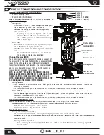
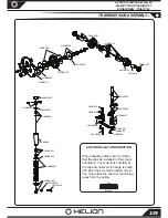
Ride height adjustment:
It is possible to adjust the ride height of your vehicle by installing and or removing adjustment clips
located directly above the shock springs.
• Adding more clips will raise the ride height of the vehicle and if done excessively may decrease stability.
• Removing clips will lower the ride height and may cause the chassis to drag on the ground.
• It is ideal to have the drive shafts above level but still allow the shocks to extend when you lift the vehicle while the vehicle is
sitting on a flat surface with the body installed. Add or remove clips to achieve the desired ride height.
Upper Shock Position:
There are multiple shock installation locations for the top mounting location of the shock towers. The
default positions have been chosen as a good starting point. Moving the shock mounting location inward will result in a slightly less
responsive feel on the front or rear of the vehicle but it will be a little more stable. Moving the shock mounting location outward will
make the truck more responsive but less stable in some conditions.
Lower Shock Position:
There are multiple shock installation locations for the lower mounting location of the shocks in the
suspension arm. The default location is outside in the front and inside on the rear suspension arm. Moving the shocks to the inside
location will result in a slightly more responsive feel on the front or rear of the vehicle but become a little less stable. This change
will also increase the vehicle’s articulation and you will notice more body roll. Always check and adjust, if necessary, the ride height
of your vehicle after moving the shock mounting locations.
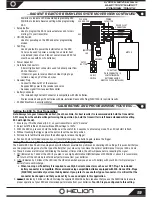
Battery mounting:
Your vehicle comes equipped with a default mount setting for a 7-Cell NiMH hump battery. It is also possible
to fit lower and higher cell count NiMH batteries and also 2s-3s LiPo batteries (we highly recommend ROAR legal dimensions and
hard cases). Ensure the foam blocks are in place to keep the battery pack from changing position in the battery tray.