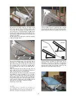
Connect the cold water inlet and hot water outlet
(1/2” male thread). Use a 15Χ2.5mm plastic pipe.
The unions that will connect the pipes with the de-
vice must have a 1/2” female thread. The plastic pipe
that you will choose should be able to withstand tem-
peratures up to 90οC and have a good tolerance at a
pressure of 10 BAR.
Insulate properly the pipes with a suitable insulating
material of at least 6 mm.
Connect the insulated pipes to the outlet and inlet of
the device (1/2” male thread) and lead them to the
place where they will be connected in order for you
to be supplied with hot water at the desired place.
Consult a plumber if you are not sure about the con-
nections.
When first filling the device with cold water, the hot
water outlet must be open (in order to let the air es-
cape) until the device is completely filled.
Securely fasten the device at the place where it will
be installed and screw it (positions 1, 2, 3, 4, photo-
graph 7) by using dowels and lag screws. Make sure
that the place where the device will be installed has
the right static strength and the appropriate contain-
ment in order for the product to be protected against
strong winds and extreme weather conditions.
(Consult your mechanic).
Lift the wooden box to an upright position, remove
and place the device in such a way that the northern
part faces the South and the southern part the North.
2
Φ 7
3
2
4
1
Φ 5
Male thread 1/2”
Φ 6
Male thread 1/2”
CAUTION:
The company bears no responsibility for incomplete or im-
proper installation of the device or for any damages that may
be caused because of that to device or to third parties.
We advise you to get an insurance against civil liability.
2
Φ 9
For the maximum performance of the device the ver-
tical plates C should be connected to the positions
1A & 1B during the summer time (April - September)
and during the winter time (October - March) to the
positions 5A & 5B respectively (Photo 8).
Φ 8
Summary of Contents for COMPACT 100
Page 4: ...4 ...


