6
1.800.221.0932
OPERATION
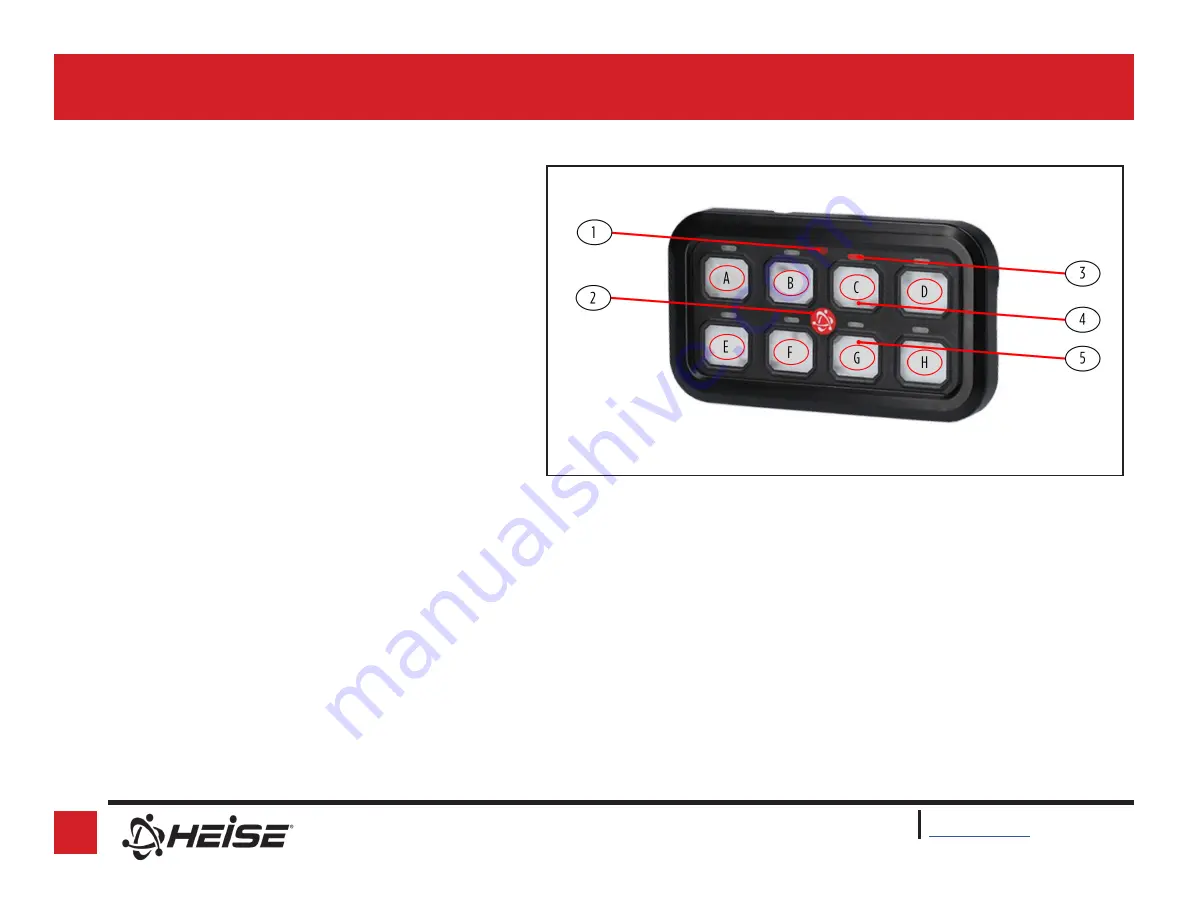
1. Power Indication LED
2. Power Button (Heise
®
Atom)
3. Circuit Activation LED
4. Label Placement Area
5. Blue LED Back-lit Area
Switch Panel
A. Accessory Circuit 1
B. Accessory Circuit 2
C. Accessory Circuit 3
D. Accessory Circuit 4
E. Accessory Circuit 5
F. Accessory Circuit 6
G. Accessory Circuit 7
H. Accessory Circuit 8
Indication
1. Red LED lights up when the HE-SWP8 is powered on .
2. Manual power activation button, press to turn on, press to turn off.
3. Red LED lights up to show the accessory circuit is on.
4. Area for placement of selected labels (decal).
5. Blue LED Illumination area; back lighting for the label.
(
Figure G
)
Accessory Circuits 1 - 8 can operate as a latched or momentary.
By default the HE-SWP8 comes out of the box set for switched mode.
To enable or disable the momentary function, follow this procedure.
Ignition must be off (No power to the Yellow wire).
1. Turn on the HE-SWP8 (Press the Heise
®
Atom then release)
2. Press and hold the Atom for 2 seconds
3. Press and hold the desired accessory button until the corresponding
LED flashes then release the button . If you are successful the LED
will flash once then turn off.
4. Test functionality, if you are unsuccessful power off and repeat
steps 1-4.
Mode


