OPERATION
Lifting
1. Ensure that the vehicle is on a flat, hard and level surface and is free to roll forward and backward during the lift.
2. Connect 1/4" NPT air nipple and air hose to lift control valve air inlet port. (See Figure 1 on page 3)
3. Loosen air vent screws (upper screws) on each hydraulic damper located on side of air cylinders.
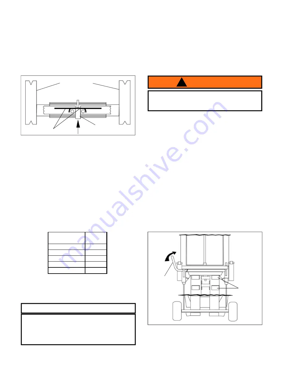
4. Insert lifting beams fully to engage lock. For low pickup height, rotate the beams 180 degrees.
5. To adjust the location of the lifting beams, push the locking pin upward from underneath and pull out the lifting beams.
(see Figure 4)
6. Adjust bumper bolt to increase ground clearance. (see Figure 2 on page 4)
7. Make sure both saddles are positioned directly under the vehicle manufacturer's recommended lift points.
8. To raise jack, slowly press the lift control valve lever toward the position marked "
UP
" until saddles contact with the lift
point.
!STOP! RELEASE GRIP ON THE LIFT CONTROL VALVE!
Confirm that the saddles are positioned correctly, then
continue to press the lever until load reaches desired height. Simply release the lever to stop.
9. Transfer the load immediately to appropriately rated jack stands.
Lowering
1. Raise load high enough to clear the jack stands, then carefully remove jack stands (
always
used in pairs).
2. Slowly lower the load by disengaging safety bar* and press lift control valve lever
"DOWN"
.
*
To disengage safety bar:
Push safety bar lever towards front end of the jack. (see Figure 5)
Note:
Refer to Table 1 for for air pressure rating for different load application
5
!
WARNING
To reduce the risk of personal injury and property
damage,
NEVER
extend lifting beams beyond
locked position
AIR PRESSURE
PSI
LOAD
(LBS)
200
14,000
180
12,000
160
11,000
140
9,500
120
8,000
Table 1. Recommended Air Pressure for Different Load
Application
Figure 4.
Retaining Bars
Locking Pin
Lifting Beams
Figure 5. Air Operated End Lift Components (rear view)
Safety Bar
Lever
Stopper
Be sure all tools and personnel are clear before
lowering load. Only attachments and/or adapters
supplied by the manufacturer shall be used. Lift
only on areas of the vehicle as specified by the
vehicle manufacturer.
! Safety Messages !
HW93692-M0
Summary of Contents for HW93692
Page 8: ...memo...


