background image

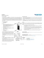
ENSURE THE AIR OUTLET OF 

HSRCH3000RF

AND 

HSRCH4500RF

 IS NEAREST TO THE WALL

OR


CORNER.


4.1 Electrical Connections. 

These  units  are  suitable  for  connection  to  a 
230/240 Volt 50 Hz single phase supply. 

The  appliance  shall  be  connected  to  the  supply 
via  an  appropriate  switched  fused  double  pole 
isolator  having  a  contact  separation  of  greater 
than 3mm. Test for correct operation and refit the 
cover. 

Fi

g.1 Air discharge of 

HSRCH3000RF 

and HSRCH4500RF

TOP OR SIDE CABLE ENTRY 

TERMINAL COVER 

For  connection  to  the  mains  supply  it  will  be 
necessary to open  the terminal cover at the side/
back  of  the  unit  to  connect  the  supply  from  the 
controls prior to refitting the cover. Wire in accord-
ance to the wiring diagrams. 

For  safety  reasons,  a  sound  earth  connection 
must always be made to the unit before it is put to 
use. The unit should be wired in accordance with 
IEE  Regulations  for  the  Electrical  Equipment  of 
Buildings.


3.1 Mounting 

The 

Heatstore

  recessed  ceiling  heaters  are  de-

signed to fit in place of a standard 600mm ceiling 
panel. 

IT  IS  ESSENTIAL  THAT  THE  CEILING  FRAME  IS 

ADE-QUATELY  SUPPORTED  TO  SUPPORT  THE  WEIGHT 

OF  THE  HEATER,  OR  THAT  THE  HEATER  IS 

INDIVIDUALLY  SUP-PORTED.   THERE  IS  PROVISION  ON 

THE  HEATER  FOR  CHAIN  OR  WIRE,  SUPPORT  OR 
MOUNTING.


The  weight  of  the 

HSRCH3000RF  and 

HSRCH4500RF

  is 7kg

It is the sole responsibility of the installer to ensure 
that  the  points  of  attachment  to  the  building  are 
sound. Care must be taken to allow complete free 
air  movement  into  the  inlet  grilles  of  the  unit  to 
ensure  the  correct  working  operation  of  the  heat-
er. Carefully  unpack the unit. The unit  is supplied 
with a length of self-adhesive foam strip.  This can 
be cut into lengths and is to be laid on the 4 sides 
of the ceiling frame .  This will ensure that the unit 
assembly  is  free  from  vibration.    The  discharge 
grille and diffuser assembly can now  be fitted  into 
the ceiling frame. 

Fig.3 Mounting supports


The wire or chain used to mount the heater can be 
attached  to  4  of  the  M6  studs  or  the  4  x  M6 
threaded inserts as shown in diagram.


3


.


Installation Details

4.

1

 Electrical Connections

Summary of Contents for HSRCH3000RF

Page 1: ...information 1 Dimensions 2 Installation Details 3 Electrical Connections 4 Operation 5 Servicing Maintenance 6 RECESSED WARM CEILING HEATERS MODELS HSRCH3000RF HSRCH4500RF INSTALLATION AND OPERATING MANUAL HSPBRF HSTIRF HSVTRF ...

Page 2: ......

Page 3: ...ats and door interlocks can be installed at the discretion and responsibility of the installer All units must be wired in accordance with I E E regulations for the Electrical Equipment of Buildings and the installer should ensure that a suitable isolating switch is connected in the mains supply 1 4 Controller RF The HSRCH3000RF and HSRCH4500RF heaters are supplied without a controller The RF model...

Page 4: ... rests with the installer to ensure that protective safety wear such as hand eye ear and head protection is used during installation of the product Do not rest anything especially ladders against the product 1 10 Standards Units conform to the European electrical standard BS EN 60335 2 30 HSRCH3000RF and HSRCH4500RF HSRCH3000RF and HSRCH4500RF 1 General Information 2 Dimensions ...

Page 5: ...recessed ceiling heaters are de signed to fit in place of a standard 600mm ceiling panel IT IS ESSENTIAL THAT THE CEILING FRAME IS ADE QUATELY SUPPORTED TO SUPPORT THE WEIGHT OF THE HEATER OR THAT THE HEATER IS INDIVIDUALLY SUP PORTED THERE IS PROVISION ON THE HEATER FOR CHAIN OR WIRE SUPPORT OR MOUNTING The weight of the HSRCH3000RF and HSRCH4500RF is 7kg It is the sole responsibility of the inst...

Page 6: ...oller can control any number of heaters providing they are in he RF range For more details please follow the instructions supplied with the controller 4 2 Electrical connections Fig 8 Heater with terminal cover open Fig 9 Terminal cover detail HSPBRF HSTIRF Heatstore RF Controllers HSVTRF 4 2 Electrical Connections 4 Operation ...

Page 7: ...obstruction of the free airflow by thermal cut outs If this happens the thermal cut outs switch off the appliance The ap pliance will not operate until the heater is discon nected from the mains supply and it has cooled down If this fault re occurs again refer to the section 6 4 fault finding 6 1 Maintanence 6 4 Fault Finding If the heater will not operate disconnect it from the mains and arrange ...

Page 8: ...7 RF RF ...

Page 9: ...8 Heatstore Unit 12 Access 18 Bristol BS11 8HT Tel 0117 9235 375 Fax 0117 9235 374 ...

Reviews: