

6
3.6
Fit the terminal cover and tighten the cable grip screws.
3.7
After fitting the heater to the wall,
ensure the electrical supply is off.
Connect the
supply cable to the connection point.
DO NOT SWITCH ON THE ELECTRICAL SUPPLY UNTIL WATER FLOWS
FROM THE HOT TAP.
3.3
Remove the terminal cover on the bottom of the unit by removing the four screws.
Check and adjust the thermostat and thermal cut-out. See TEMPERATURE
SETTINGS.
3.4
Strip
the outer sheath of the cable and the insulation of the conductors to the
required lengths, ensuring that the outer sheath will be held in the cable grip in the
cover when the connections are made. Slacken off the the cable grip screws and
thread the cable through the grip..
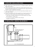
3.0 INSTALLATION - ELECTRICAL REQUIREMENTS
WARNING: This appliance must be earthed.
It is suitable for 230/240V a.c. supply only.
Installation must be in accordance with BS 78671, Requirements for Electrical
Installations (I.E.E. Wiring Regulations.)
3.1
The electrical supply should be fused at 13 A and be via a readily accessible
double pole isolating switch with a contact separation of at least 3mm in both
poles.
3.2
The connection between the heater and the connection point should be made with
heat resisting (85°C) cable with a minimum cross sectional area of 1.5 mm
2
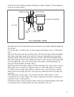
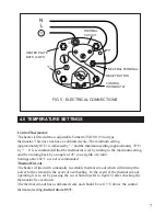
3.5
Connect the brown (or red) conductor to the thermal cut-out (L).
Connect the blue (or black) conductor to the neutral element teminal.
Connect the green/yellow (or green) conductor to the stud marked .
Refer to
figure 5


