Heatmaster HM 101 Installation And Operating Instructions Manual Download Page 13

12

COMMISSIONING

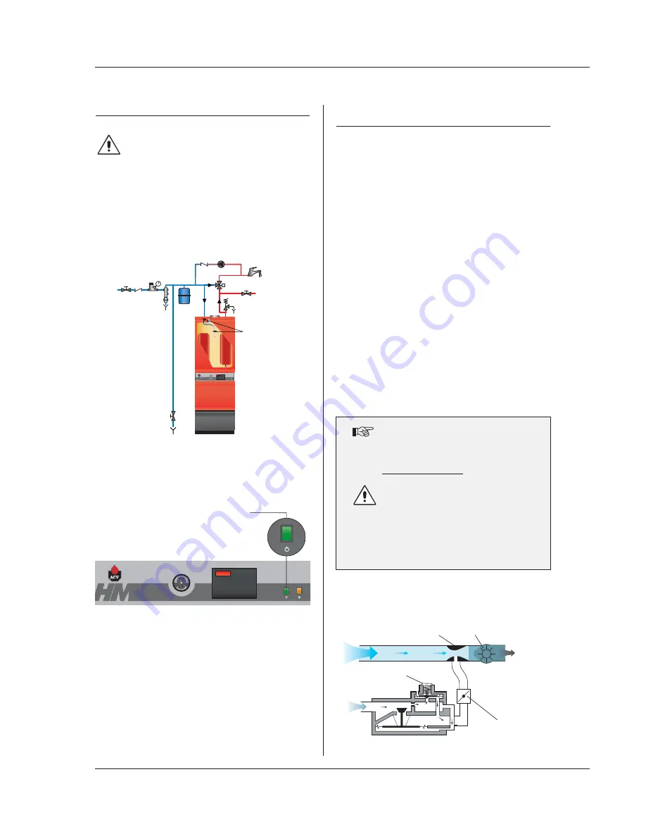
FILLING THE HOT WATER AND HEATING CIRCUITS

IMPORTANT
The hot water tank must be pressurised before the
heating circuit is filled.

1.

Close the primary circuit filling valves (11).

2.

Open the stop valve (1) and the drawoff tap (8).
When water flows out of the tap, the hot water tank is full and
the drawoff tap (8) should be closed.

3.

Fill the primary (heating) circuit by opening the valves (11) and
pressurising to 1 bar.

4.

Open the automatic air vent located on top of the boiler.

IMPORTANT - the screw cap must be left loose to allow future
automatic venting to take place.

5.

After venting the air from the system, bring the pressure up to
the static head plus 0.5 bar: 1.5 bar = 10m and 2 bar = 15 m.

6.

Check that the electrical connection and boiler room ventilation
conform to the relevant standards.

7.

Switch the on/off switch to the ON position.

8.

Set the temperature settings 

(see pages 15-16)

.

9.

Check the gas supply pressure 

(see page 13)

.

10. When the burner operates, check the chimney connection for

leaks.

11. After 5 minutes of operation, turn the boiler off and vent the heating

circuit system again maintaining the water pressure at 1 bar.

12. Then restart the unit and check the combustion 

(see page 13)

.

Burner troubleshooting

See page 15-17

Spare parts

Refer to the specific document available from ACV or your distributor.

ACV BG 2000-M MODULATING
PREMIX GAS BURNERS

Description of operation:

The BG 2000-M modulating burner continually adjusts output to
demand, improving operating efficiency.
The burner tube is coated with metal fibre (NIT) which, in addition to
its remarkable heat exchange capabilities, gives greater durability.

The main components are a venturi and one (model 71) or two
(model 101) gas valves, technology specially developed by
Honeywell for low Nox premix air/gas burners with automatic ignition
and ionisation flame detection.
The pressure at the gas valve outlet is equal to the air pressure in
the neck of the venturi, less the offset. The fan sucks combustion air
through the venturi, into which the gas inlet emerges.
As it passes through, the air produces a pressure differential in the
constriction of the venturi and sucks the gas into the venturi outlet.
A perfect mix of air and gas then passes through the fan to the
burner tube.

This design ensures very quiet and safe operation:

If there is an air blockage, the pressure differential in the venturi
falls, the gas flow diminshes, the flame goes out and the gas
valve closes: the burner is in safety shutdown mode.

If there is a blockage in the chimney outlet, the air flow diminishes,
and the same reactions as those described above cause the
burner to shut down in safety mode.

The BG 2000-M burner fitted to the HeatMaster 71 and 101 is
regulated by a MCBA controller (Honeywell) which controls burner
operating safety as well as temperature modulation.

BG 2000-M burners are preset at the factory
for natural gas.

Conversion to propane:

Not applicable for Belgium.

Conversion kit included with burner comprising:
- Cap(s)
- Nameplate(s)
- Sticker with settings.
- Mounting instructions.

Air-gas mixture control system

1

2

3

4

5

2

6

7

8

9

10

12

11

Air

Venturi

Fan

Air - gas

mixture

Gas flow

regulating screw

Offset regulation

screw

Gas

BURNER FEATURES

Summary of Contents for HM 101

Page 1: ...66401100 excellence in hot water Installation Operating and Servicing Instructions HeatMaster HM 71 HM 101...

Page 2: ...incorrect installation or from the use of components or fittings not specified by ACV Failure to observe instructions regarding tests and test procedures can result in personal injury or pollution ris...

Page 3: ...e most hot water and heating demands can be met Indeed when used in conjunction with HR and Jumbo hot water storage tanks the Heatmaster can supply even the largest hot water requirement Standard equi...

Page 4: ...ating return Combustion chamber Burner chamber plate Primary circuit Primary safety valve Low water pressure switch Detector NTC1 and NTC2 Casing front panel Primary expansion vessel Domestic cold wat...

Page 5: ...pane Natural gas propane Maximum Input kW 20 69 9 25 107 22 110 Maximum Output kW 63 0 96 8 Maintenance loss at 60 C of rated value 0 5 0 4 Total capacity L 239 0 330 0 Primary circuit capacity L 108...

Page 6: ...om 20 to 90 C 2 Hot water mode ON OFF 3 Heating mode ON OFF 4 Heating setting adjustable from 60 to 90 C Parameters accessible in servicing Main default settings Hot water priority active Heating dema...

Page 7: ...ust be installed by an approved heating engineer in accordance with the prevailing local standards and regulations Flue size should not be less then the outlet size of the boiler Chimney connection ty...

Page 8: ...many and Luxembourg C53 C13 C33 2 m min 150 min 120 Maximum length concentric 6 metres Maximum length parallel 12 metres Note a 90 degree bend 1 metre equivalent length A condensation drain outlet mus...

Page 9: ...ies a temperature and pressure relief valve must be fitted consult your ACV stockist for assistance Example of hot water connection with thermostatic mixer 1 Stop cock 2 Non return valve 3 Pressure re...

Page 10: ...to the primary circuit calculate the expansion capa city necessary for the total volume of the heating system Refer to the technical instructions from a relevant manufacturer of expansion vessels Exam...

Page 11: ...mounted on the alarm module will now be actived as described below 1 Alarm This contact closes if the MCBA is in lock out 2 External gas valve burner run indication This contact closes if a heat reque...

Page 12: ...nection 5 Central heating pump 6 HeatMaster shunt pump 7 Room thermostat 8 Low water pressure switch 9 Primary temperature detector NTC 1 10 Primary temperature detector NTC 2 11 Hot water temperature...

Page 13: ...er tube is coated with metal fibre NIT which in addition to its remarkable heat exchange capabilities gives greater durability The main components are a venturi and one model 71 or two model 101 gas v...

Page 14: ...w m3 h 2 46 8 60 3 80 13 17 Gas G31 37 50 mbar I 3P Flow m3 h 0 82 2 86 0 94 4 50 Pressure drop combustion chamber mbar 0 6 1 4 Flue gas temperature net C 172 165 Mass flow rate of combustion products...

Page 15: ...rn OFF the on off switch on the boiler control panel and isolate external electrical supply 2 Turn off the gas supply to the boiler 3 Remove the flue to gain access to the top of the boiler 4 Remove t...

Page 16: ...our installer will have informed you of this value at the time of installation see Commissioning Section Filling the hot water and heating circuits If the pressure falls below 1 bar the boiler water p...

Page 17: ...behind a flap on the front of the boiler see picture on page 16 Standby Mode Standby Mode is the normal operation display setting The first digit shows the boiler sequence This sequence relates to cu...

Page 18: ...ck that sensor NTC2 is propely housed in its pocket if so change sensor NTC2 check that the shunt pump is operating and if so vent the boiler if the fan is turning check the PWM connection if the prob...

Page 19: ...Efficiency Gas pressure SERVICE RECORD Date serviced CO2 min load CO2 max load Gas LPG Remarks Name and signature Flue gas T Efficiency Gas pressure Date serviced CO2 min load CO2 max load Gas LPG Re...

Page 20: ...84 E MAIL sales triangletube com ARGENTINA TECNOPRACTICA ALFEREZ BOUCHARD 4857 1605 CARAPACHAY BUENOS AIRES TEL 54 11 47 65 33 35 FAX 54 11 47 65 43 07 E MAIL jchas tecnopractica com BRAZIL SIMETAL IN...

Reviews: