


20
Heatilator • ICON DV-IDV Series • 4042-575 Rev G • 09/07
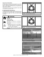
W
ALL
1-1/2 in.
(38 mm)
3 in.
(76 mm)
No combustible
framing to be
located within
shaded area.
2 x 4 or
2 x 6
header
Sheetrock
Air space clearance to
bottom and sides of
horizontal pipe must be
at least 1 in. (25 mm)
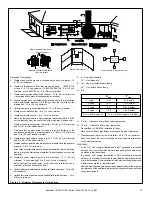
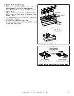
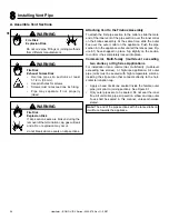
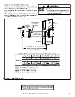
B. Wall Penetration Framing
• Wherever a combustible wall is penetrated, the hole must
be framed with a wall shield
fi
restop. This shield maintains
minimum clearances and restricts cold air in
fi
ltration.
• If the wall being penetrated is of noncombustible materials
(material which will not ignite or burn, or has a UL
fi
re rating
of zero), a 9 in. (229 mm) diameter hole is acceptable.
• Whenever a wall is penetrated the wall shield
fi
restop
is only required on one side and no heat shield is
necessary.
• If your local inspector requires the wall shield
fi
restop on
both sides of the wall, then both wall shield
fi
restops must
have a heat shield attached to them.
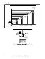
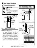
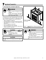
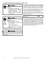
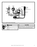
A. Pipe Clearances to Combustibles
Fire Risk
Explosion Risk
Maintain vent clearance to combustibles as
speci
fi
ed.
• Do not pack air space with insulation or
other materials.
Failure to keep insulation or other materials
away from vent pipe may cause
fi
re.
WARNING
Figure 6.1 Minimum Top Vented DV Pipe Clearances
3 in. (76 mm)
top clearance
1 in. (25 mm)clearance
bottom & sides
1 in. (25 mm)
clearance
around vertical
sections
3 in. (76 mm)
top clearance
1 in. (25 mm)
clearance
bottom & sides
Heat
Shield
Wall
Shield
Firestop
Heat
Shield
WALL
Note: Heat shields MUST overlap by a minimum of 1-1/2 in. (38 mm).
The
heat shield is designed to be used on a wall 4 in. to 7-1/4 in. (102 mm to
184 mm) thick.
If wall thickness is less than 4 in. (102 mm) the existing heat
shields must be field trimmed. If wall thickness is greater than 7-1/4 in. (184
mm) a DVP-HSM-B will be required.
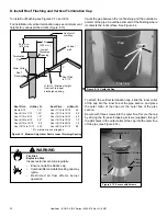
Figure 6.2 Minimum Horizontal Venting Clearances to Combus-
tible Materials
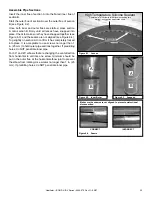
A*
Framing should be
constructed of 2 X 4
lumber or heavier.
The center of the
framing hole is
1 in. (25mm) above
the center of the
horizontal vent pipe.
Vent framing hole.
DO NOT PACK WITH
INSULATION OR
OTHER MATERIAL.
* Measured to
center of pipe.
10 in.
12 in.
Figure 6.3 Exterior Wall Hole
6
6
Vent Clearances and Framing
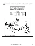
Appliance
A
IDV4833IT
64-1/8 in./1629 mm
IDV4833ILT
64-1/8 in./1629 mm
IDV4833IH
64-1/8 in./1629 mm
IDV4833ILH
64-1/8 in./1629 mm
IDV6247IT
68-5/8 in./1743 mm
IDV6247ILT
68-5/8 in./1743 mm
IDV6247IH
68-5/8 in./1743 mm
IDV6247ILH
68-5/8 in./1743 mm
¨
¨
¨