4
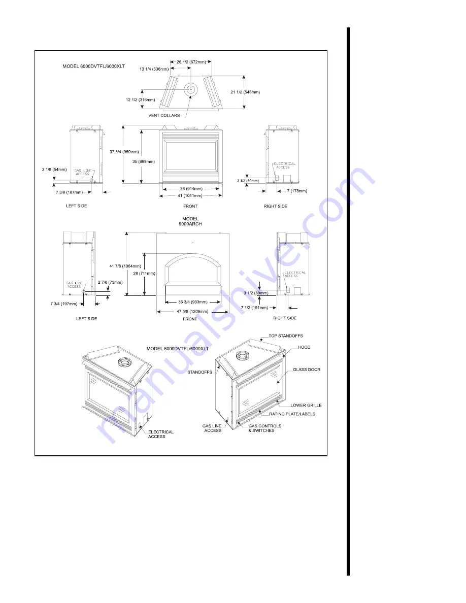
Figure 2. Diagram of 6000DVTFL, 6000XLT and 6000ARCH
Page 1: ...ian Patent 1 297 746 Installers Guide WARNING IMPROPER INSTALLATION ADJUSTMENT ALTERATION SERVICE OR MAINTENANCE CAN CAUSE INJURY OR PROPERTY DAMAGE REFER TO THIS MANUAL FOR ASSISTANCE OR ADDITIONAL I...
Page 2: ...an be performed The warranty exclusions and limitations of liability are effective upon installation of the fireplace Subject to the conditions set forth herein HEAT N GLO FIREPLACE PRODUCTS INC HEAT...
Page 3: ...Vent System Approvals 8 B Installing Vent Components 17 C Vent Termination 23 Step 4 Positioning Leveling and Securing the Fireplace 28 Step 5 The Gas Control Systems 28 Step 6 The Gas Supply Line 29...
Page 4: ...odes in Canada The appliance must be electrically grounded in accordance with local codes or in the absence of local codes with the National Electric Code ANSI NFPA No 70 in the United States or to th...
Page 5: ...packaged separately and must be field installed Models 6000DVTFL 6000ARCH 6000XLT SL 42DVT Read all of the instructions before starting the installation Follow these instructions carefully during the...
Page 6: ...Framing and finishing details Whether optional accessories devices such as a fan wall switch or remote control are desired If the fireplace is to be installed on carpeting or tile or on any combustibl...
Page 7: ...4 Figure 2 Diagram of 6000DVTFL 6000XLT and 6000ARCH...
Page 8: ...5 Figure 3 Diagram of SL 42DVT...
Page 9: ...s of Top of Front Floor Fireplace Fireplace Fireplace Ceiling 36 inches 0 1 2 inch 1 2 inch 3 1 2 inches 31 inches 914 mm 13 mm 13 mm 89 mm 787 mm The minimum clearance to a perpendicular wall extendi...
Page 10: ...et in place Framing should be positioned to accommodate wall coverings and fireplace facing material The diagram below shows framing reference dimensions CAUTION MEASURE FIREPLACE DIMENSIONS AND VERIF...
Page 11: ...e 90 elbow assemblies The relationships of vertical rise to horizontal run in vent configurations using 90 elbows MUST BE strictly adhered to The rise to run relationships are shown in the venting dra...
Page 12: ...8 8 1 2 5 1 16 8 12 11 5 8 8 5 8 11 15 16 DV 36D 35 3 4 47 3 4 DV 48D 5 3 4 8 3 4 11 3 4 DV 12D DV 09D DV 06D 6 5 32 156 mm 7 3 8 5 7 8 187 mm 149 mm 8 1 2 216 mm 8 5 8 220 mm 11 15 16 303 mm 11 5 8 2...
Page 13: ...10 Figure 8 SL D Series Direct Vent Component Specifications 4 inch inner pipe 6 5 8 inch outer pipe...
Page 14: ...11 Figure 9 Vertical Venting VERTICAL VENTING V FT 40 MAX 12 4 M NOTE MODEL 6000 ARCH A 12 inch length of straight vent pipe MUST be the first vent component attached to the unit V CAP...
Page 15: ...RCH A12 INCHLENGTHOFSTRAIGHT VENT PIPE MUST BE THE FIRST VENT COMPONENT ATTACHED TO THE UNIT FOR 8000DVTFL 6000DVTFL 6000XLT NOTE IF A 90 ELBOW IS FIRST ATTACHED TO THE UNIT THE MAXIMUM HORIZONTAL RUN...
Page 16: ...305 mm 6 MAX 1 86 m 3 MAX 914 mm 2 MIN 610 mm 12 MAX 3 72 m 6 MAX 1 83 m 3 MIN 914 mm 18 MAX 5 58 m 9 MAX 2 74 m 4 MIN 1 22 m 24 MAX 8 44 m 12 MAX 3 66 m 20 MAX 6 2 m 24 MAX 8 44 m 12 MAX 3 66 m 21 IN...
Page 17: ...12 MAX 3 72 m 6 MAX 1 86 m 3 MIN 914 mm 18 MAX 5 58 m 9 MAX 2 74 m 4 MIN 1 22 m 24 MAX 8 44 m 12 MAX 3 66 m 24 MAX 8 44 m 12 MAX 3 66 m 21 IN CANADA 6 5 m NOTE V V1 MAX 20 6 2 m NOTE MODEL 6000 ARCH A...
Page 18: ...14 mm 18 MAX 5 58 m 9 MAX 2 74 m 4 MIN 1 22 m 24 MAX 8 44 m 12 MAX 3 66 m 24 MAX 8 44 m 12 MAX 3 66m NOTE H H1 MAX 24 8 44 m 8000 6000 s NOTE H H1 MAX 12 3 66 m SL 42DVT V V1 MAX 20 6 2 m H1 H1 H V1 V...
Page 19: ...THREE 3 90 ELBOWS V FT H H1 FT 8000 6000 s H H1 FT SL 42DVT 1 MIN 305 mm 6 MAX 1 86 m 3 MAX 914 mm 2 MIN 610 mm 12 MAX 3 72 m 6 MAX 1 86 m 3 MIN 914 mm 18 MAX 5 58 m 9 MAX 2 74 m 4 MIN 1 22 m 24 MAX 8...
Page 20: ...e up rotate the pipe section clockwise about one quarter 1 4 turn The vent pipe is now locked together The first 90 elbow installed in the vent system of a rear venting fireplace MUST BE in a vertical...
Page 21: ...dding Vent Components To continue adding vent components in accordance with the pre planned vent system configuration Ensure that each succeeding vent component is securely fitted and locked into the...
Page 22: ...ting Components 3 Install Support Brackets For Horizontal Runs The vent system must be supported every five 5 feet of horizontal run by a horizontal pipe support To install support brackets for horizo...
Page 23: ...r Horizontal Runs Firestops are REQUIRED on both sides of a combustible wall through which the vent passes NOTE Model DVK 01TRD and SLK 01TRD do not need an exterior firestop on an exterior combustibl...
Page 24: ...vent run Figure 20 Heat Shield Interior and Exterior Firestops For Vertical Runs One ceiling firestop is REQUIRED at the hole in each ceiling through which the vent passes To install firestops for ve...
Page 25: ...X 254 mm for SLD series pipe hole through the ceiling using the centerpoint previously marked Frame the hole with framing lumber the same size as the ceiling joists 1 Cut the ceiling hole 2 Add the ne...
Page 26: ...ng of the Installing Vent Components sec tion The termination kit should pass through the wall firestops from the exterior of the building Adjust the termination cap to its final exterior posi tion on...
Page 27: ...op Figure 24 Round and Trapezoid Termination Caps WARNING THE BOTTOM OF THE VENT TERMINATION CAP MUST BE A MINIMUM OF 12 INCHES 305 MM ABOVE GROUND LEVEL GRADE THE TOP OF THE CAP MUST BE A MINIMUM OF...
Page 28: ...3 ft U S A clearance to service regulator vent outlet 6 ft Canada J 9 U S A clearance to non mechanical air supply inlet to building 12 Canada or the combustion air inlet to any other appliance K 3 ft...
Page 29: ...er the same size as the roof rafters and install the frame securely Flashing anchored to the frame must withstand heavy winds Continue to install concentric vent sections up through the roof hole for...
Page 30: ...he vent system Attach a flashing to the roof using nails and use a non hardening mastic around the edges of the flashing base where it meets the roof Attach a storm collar over the flashing joint to f...
Page 31: ...se models Standing Pilot Ignition and Direct Spark Ignition DSI Model 6000XLT has Standing Pilot Ignition only Model 6000ARCH has DSI only Standing Pilot Ignition System This system includes millivolt...
Page 32: ...lexible gas connector are connected to the 1 2 inch 13 mm inlet of the control valve A 1 8 inch 3 mm N P T plugged tapping accessible for test gauge connection should be provided for in the gas supply...
Page 33: ...s Pressure w c w c A one eighth 1 8 inch 3 mm N P T plugged tapping is provided on the outlet side of the gas control for a test gauge connection to measure the manifold pressure To measure inlet pres...
Page 34: ...alled junction box before the fireplace is permanently installed Remote Wall Switch Position the remote wall switch in the desired position on a wall Run a maximum of 25 feet 7 8 m or less length of 1...
Page 35: ...This appliance requires that 110 120 VAC be wired to the factory installed junction box Maintain correct polarity when wiring the junction box Optional Accessories Optional fan and remote control kits...
Page 36: ...combustible materials may be used to cover the black fireplace front Figure 33 Minimum Vertical and Maximum Horizontal Dimensions of Combustibles above Fireplace WARNING WHEN FINISHING THE FIREPLACE N...
Page 37: ...ify the air inlet outlet grilles When overlapping on both sides leave enough space so that the bottom grille can be lowered and the trim door removed CAUTION IF JOINTS BETWEEN THE FINISHED WALLS AND T...
Page 38: ...fireplace The bag labeled Golden Ember GE 93 is flame colorant material The bag labeled Glowing Ember 050 721 is standard glowing ember material To place the ember material Remove the wing nuts and g...
Page 39: ...he unit Figure 35 Glass Assembly CAUTION HAND TIGHTEN THE WING NUTS BUT BE CAREFUL NOT TO OVERTIGHTEN 1 Place the ember material onto the top of the burner Figure 36 Placement of the Ember Material CA...
Page 40: ...mall amount of air will be in the gas supply lines When first lighting the fireplace it will take a few minutes for the lines to purge themselves of this air Once the purging is complete the fireplace...
Page 41: ...his procedure at your next servicing For more information see Placing Ember Material in this manual Cleaning Once annually Qualified Brush or vacuum the control Burner Service compartment fireplace lo...
Page 42: ...E CERAMIC INSULATORS CAN CAUSE NUISANCE LOCKOUTS AND ELECTRODE FAILURE DSI IGNITION CERAMIC INSULATOR 3 16 5 mm IGNITOR 1 2 13mm Figure 37 Burner Flame Patterns MAKE SURE THE FLAMES ARE STEADY NOT LIF...
Page 43: ...g Pilot Only PART PART DESCRIPTION PART NUMBER Valve LP 8000 6000 S SRV60 523 Valve NG 8000 6000 S SRV60 522 Valve LP SL 42DVT SRV60 521 VAlve NG SL 42DVT SRV60 520 Piezo Ignitor SRV60 513 Thermopile...
Page 44: ...00ARCH SL 42DVT PART PART DESCRIPTION PART NUMBER DSI Valve LP SRV77 501 DSI Valve NG SRV77 500 Transformer SRV60 599 DSI Module SRV420 592 Electrode SRV77 591 Burner Tube 8000DVTFL SRV410 303 6000DVT...
Page 45: ...0DVTFL NG 6000XLT NG 6000ARCH NG SRV422 176A 6000DVTFL LP 6000XLT LP 6000ARCH LP SRV422 175A Burner Orifice 8000DVTFL NG SRV67 800 8000DVTFL LP SRV79 803 6000DVTFL NG SRV79 831 6000DVTFL LP SRV79 803...
Page 46: ...FL 6000DVTFL LOGS 6FL 6000XLT LOGS CAMP SL 42DVT LOGS SL42 Bottom Right Refractory SL 42DVT SRV486 370 Bottom Left Refractory SL 42DVT SRV486 371 Grate Assembly SL 42DVT SRV486 360A ACCESSORY PART DES...