background image

8

injured  by  hot  water  than  others.    These  include  the 

elderly, children, the infirm, or physically/ developmentally 

disabled.  If anyone using hot water in you home fits into 

one of these groups, or if there is a local code or state law 

requiring a maximum water temperature at the hot water 

tap, then you must take special precautions.  In addition to 

using the lowest possible temperature setting that satisfies 

your hot water needs, a means such as a 

MIXING VALVE


should be used at the hot water taps used by these people 

or at the water heater.


MIXING VALVES 

for  reducing  point  of  use  temperature 

are available and are to be set at a maximum of 125˚F.  

Consult a qualified installer or service agency.  Follow all 

manufacturer’s instructions for installation of these valves.  

Before  changing  the  factory  setting  on  the  thermostat, 

read the 

Temperature Regulation

 section in this manual.

CONTAMINATED WATER

  This water heater shall not be connected to any heating 

system(s) used with a non-potable water heating appliance.

  Toxic Chemicals, such as those used for boiler treatment, 

shall not be introduced into this system.

CIRCULATING PUMP

  Field installed circulating pumps should be of all bronze 

construction.

INSULATION BLANKETS
 

Insulation  blankets  are  available  to  the  general  public 

for  external  use  on  electric  water  heaters  but  are  not 

necessary with this product.  The purpose of an insulation 

blanket  is  to  reduce  the  standby  heat-loss  encountered 

with  storage  tank  heaters.    Your  water  heater  meets  or 

exceeds  the  EPACT  and ASHRAE/  IES  90.1  standards 

with respect to insulation and standby loss requirements, 

making an insulation blanket unnecessary.

  Should you choose to apply an insulation blanket to this 

heater, you should follow these instructions below.  Failure 

to  follow  these  instructions  can  result  in  fire,  serious 

personal injury, or death.
  Do not cover the Temperature and Pressure (T&P) Valve 

with an insulation blanket.

  Do not over the instruction manual.  Keep it on the side 

of the water heater or nearby for future reference.

  Obtain new warning and instruction labels for placement 

on the blanket directly over the existing labels.

TEMPERATURE AND PRESSURE RELIEF VALVE
 

This water heater is provided with a properly rated/ sized 

and  certified  combination  Temperature  and  Pressure 

Relief  Valve.    The  valve  is  certified  by  a  nationally 

recognized  testing  laboratory  that  maintains  periodic 

inspection of production of listed equipment of materials 

as  meeting  the  requirements  for  Relief  Valves  for  Hot 

Water Supply Systems, ANSI Z21.22 · CSA 4.4, and the 

code requirements of ASME.

  If replaced, the new valve must meet the requirements of 

local codes, but not less than a combination Temperature 

and  Pressure  Relief  Valve  rated/  sized  and  certified  as 

indicated in the above paragraph.  The new valve must be 

marked with a maximum set pressure not to exceed the 

marked hydrostatic working pressure of the water heater 

(150 psi = 1,035 kPa) and a discharge capacity not less 

than the water heater BTU/ hr or KW input rate as shown 

on the water heater’s model rating plate.

  For  safe  operation  of  the  water  heater,  the  temperature 

and  pressure  relief  valve  must  not  be  removed  from  its 

designated opening, nor plugged.  The T&P Valve must 

be  installed  directly  into  the  fitting  of  the  water  heater 

designated for the relief valve.  Install the discharge piping 

so that any discharge will exit only within 6 inches above, 

or at any distance below, the structural floor.  Be certain 

that no contact is made with any live electrical part.  The 

use  of  more  than  four  elbows  can  cause  restriction  and 

reduce the discharge capacity of the valve.

  No valve or other obstruction is to be placed between the 

relief valve and the tank.  Do not connect discharge piping 

directly to the drain unless a 6-inch air gap is provided.  To 

prevent bodily injury, hazard to life, or property damage, 

the  relief  valve  must  be  allowed  to  discharge  water  in 

adequate quantities should circumstances demand.  If the 

discharge pipe is not connected to a drain or other suitable 

means, the water flow may cause property damage.


INSTALLATION CONTINUED

WARNING

TOXIC CHEMICAL HAZARD

Do not connect to non-potable water system.

WARNING

EXPLOSION HAZARD

Temperature and Pressure Relief 

Valve must comply with ANSI 

Z21.22 and ASME code.
Properly-sized Temperature and 

Pressure Relief Valve must be 

installed in opening provided.
Failure to install relief valve can 

result in overheating and excessive 

tank pressure.
Failure to follow these instructions 

can cause serious injury or death.

INSTALLATION CONTINUED ON NEXT PAGE

Summary of Contents for SSL-10

Page 1: ...truction manual and the safety messages herein before installing operating or servicing this water heater Failure to follow these instructions and safety messages could result in death or serious injury This manual must remain with the water heater WARNING If the water heater becomes immersed in water up to or above the level of the bottom of the element doors the heater should be examined by a qu...

Page 2: ...uation which if not avoided could result in minor or moderate injury CAUTION used without the safety alert symbol indicates a potentially hazardous situation which if not avoided could result in property damage All safety messages will generally tell you about the type of hazard what can happen if you do not follow the safety message and how to avoid the risk of injury IMPORTANT DEFINITIONS Qualif...

Page 3: ...LD BE NO SMOKING OR OPEN FLAME NEAR THE FAUCET AT THE TIME IT IS OPEN WARNING EXPLOSION HAZARD Flammable hydrogen gases may be present Keep all ignition sources away from faucet when turning on hot water When servicing this unit verify the power to the unit is turned off prior to opening the control cabinet door WARNING EXPLOSION HAZARD Overheated water can cause water tank explosion Properly size...

Page 4: ...de authority having jurisdiction and the requirements of the power company In the absence of local codes the installation must comply with the latest editions of the National Electrical Code NFPA 70 or the Canadian Electrical Code CSA C22 1 The National Electrical Code may be ordered from National Fire Protection Association 1 Batterymarch Park Quincy MA 02269 The Canadian Electrical Code is avail...

Page 5: ... F 40 F 54 F 60 F 72 F 80 F 90 F 100 F 108 F 120 F 126 F Non Simultaneous Operation 1500 1 5 17 15 11 10 8 8 7 6 6 5 5 2000 2 0 23 20 15 14 11 10 9 8 8 7 6 2500 2 5 28 25 19 17 14 13 11 10 9 8 8 3000 3000 3 0 34 30 23 20 17 15 14 12 11 10 10 4000 4000 4 0 45 41 30 27 23 20 18 16 15 14 13 4500 4500 4 5 51 46 34 30 25 23 20 18 17 15 14 5000 5000 5 0 56 51 38 34 28 25 23 20 19 17 16 6000 6000 6 0 68 ...

Page 6: ...ER WATTS LOWER CIRCUIT INTERLOCK 1 PH 3 PH 1 PH 3 PH RATED CAPACITY WORKING PRESSURE MAX PSI WATTS TOTAL WATTS CONNECTED STANDBY LOSS Conforms to UL 1453 Certified to CAN CSA STD C22 2 No 110 94 MASS Approval P1 0119 315 SSL 10 20 30 40 50 SSN 40 50 60 80 119 Conforms to UL1453 for Electric Commercial Water Heaters Certified to CAN CSA STD C22 2 No 110 94 ...

Page 7: ...RAIN VALVE T P VALVE MUST BE PIPED A MAX OF 6 FROM FLOOR DRAIN SHUTOFF VALVE WATTS LF301 DIELECTRIC UNION W 4 CU TUBE SUPPLIED W UNIT COLD WATER INLET HOT WATER SUPPLY ACCESS PANEL T P VALVE WATTS 3 4 LF301 DIELECTRIC UNION W 4 CU TUBE SUPPLIED W UNIT INSTALL VACUUM RELIEF IN COLD WATER INLET LINE AS REQUIRED BY LOCAL CODES INSTALL THERMAL EXPANSION TANK IF CHECK VALVE OR PRESSURE REDUCING VALVE I...

Page 8: ... replaceable parts such as thermostats drain valve and relief valve Adequate clearance for servicing this water heater should be considered before installation such as changing the anodes etc CAUTION PROPERTY DAMAGE HAZARD All water heaters eventually leak Do not install without adequate drainage INSTALLATION REQUIRED ABILITY Installation and service of this water heater requires ability equivalen...

Page 9: ...ter heater is provided with a properly rated sized and certified combination Temperature and Pressure Relief Valve The valve is certified by a nationally recognized testing laboratory that maintains periodic inspection of production of listed equipment of materials as meeting the requirements for Relief Valves for Hot Water Supply Systems ANSI Z21 22 CSA 4 4 and the code requirements of ASME If re...

Page 10: ...al and replace the T P Valve with a properly rated sized new one If you do not understand these instructions or have any questions regarding the T P Valve call the toll free number listed on the back cover of this manual for technical assistance CLOSED WATER SYSTEMS Water supply systems may because of code requirements or such conditions as high line pressure among others have installed devices su...

Page 11: ...element heater equipped with high limit control and single phase power input 2 Four wire H 8 circuit for dual element heater equipped with two high limit controls single phase or three phase power input The heater with dual elements is factory wired for connection to a three wire three phase delta branch circuit non sumultaneous operation In addition a ground conductor is required Element connecti...

Page 12: ...t Burial Based on Ambient Temperature of 86 F These ampacities relate only to conductors described in Table 310 13 in Code For ambient temperatures that over 86 F see Correction Factors Note 13 in Code Size Temperature Rating of Conductor See Table 310 13 in Code AMG MCM 140 F 167 F Types RUW 14 2 T TW UF Types RH RHW RUH 14 2 THW THWN XHHW USE 18 16 14 15 15 12 20 20 10 30 30 8 40 45 6 55 65 4 70...

Page 13: ...sary 3 DepresstheredmanualresetbuttononeachThermostat ECO combination control See Figure 5 6 7 or 8 4 Turn on the electrical disconnect switch 5 Observe the operation of the electrical components during the first heating cycle Use care as the electrical circuits are energized 6 Close the front panel or top access cover Temperature control and contactor operation should be checked by allowing heate...

Page 14: ...for these three settings are LO 140 F MED 160 F HI 181 F These thermostats are set from the factory at the LO setting The over temperature device ECO High Limit attached to each thermostat has a manual reset The H 2 circuit thermostat is adjustable from approximately 130 F to 170 F see Figure 6 these thermostats are set from the factory at approximately the 125 F setting The over temperature devic...

Page 15: ...tify and locate water heater components NOT ENOUGH OR NO HOT WATER 1 Be certain the electrical disconnect switch serving the water heater is in the ON position 2 Check the fuses The electrical disconnect switch usually contains fuses 3 If the water was excessively hot and is now cold the high limit switch may have activated Large demands require a recovery period to restore water temperature 4 The...

Page 16: ...ruction Manual for assistance in locating a service agency in your area REPLACEMENT PARTS Call the phone number on the back cover of this Instruction Manual for assistance in locating replacement parts When ordering parts specify complete model no see rating plate quantity and name of the part desired Standard hardware items should be purchased locally TROUBLESHOOTING CHECKLIST CONTINUED LEAKAGE C...

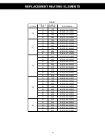
Page 17: ... ELEC_EL 208V1500W 2 0 2000 ELEC_EL 208V2000W 2 5 2500 ELEC_EL 208V2500W 3 0 3000 ELEC_EL 208V3000W 4 5 4500 ELEC_EL 208V4500W 5 0 5000 ELEC_EL 208V5000W 5 5 5500 ELEC_EL 208V5500W 6 1 6100 ELEC_EL 208V6100W 240 1 5 1500 ELEC_EL 240V1500W 2 0 2000 ELEC_EL 240V2000W 2 5 2500 ELEC_EL 240V2500W 3 0 3000 ELEC_EL 240V3000W 4 5 4500 ELEC_EL 240V4500W 5 0 5000 ELEC_EL 240V5000W 5 5 5500 ELEC_EL 240V5500W...

Page 18: ...r taste of water Failure to conduct authorized factory start up if required Alterations to the water heater Non outdoor heaters installed outdoors Damages due to a failure to allow for thermal expansion Heat exchanger failure due to lack of adequate proper supply of water Heaters moved from their original location Service trips to explain proper installation use or maintenance of the product unit ...

Page 19: ...18 ...

Page 20: ...HEAT FLO INC P O BOX 612 UXBRIDGE MA 01569 508 278 2400 www heat flo com ...

Reviews: