


Heat Controller, Inc.
MGD-B SERIES GAS FURNACE
Installation Instructions
Mortex Products Inc. / Fort Worth, TX 76106
G18D Installation Instructions
4
RETURN AIR
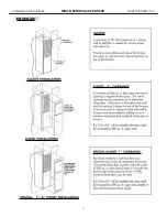
ALCOVE INSTRUCTION
The furnace may be installed free standing or in an
alcove with a free flow of air back to the furnace. A
minimum of 18” shall be provided at the front for return
air and service access.
CLOSET INSTALLATION – 6 in.
Note: If return air is through a side wall, there must be a
minimum of 6-in. clearance from side wall to furnace in
addition to 6-in. minimum clearance from inside of closet
door to front of furnace.
If a louvered door complying with the minimum air
requirements is used, the front clearance my be reduced
to 1”.
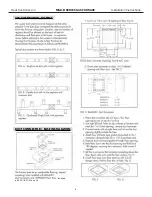
CLOSET INSTALLATIONS
Additional Requirements:
Concerning under floor or ceiling return air systems, the
following item (1 – 10) must be adhered to:
1. The return-air opening into the closet, regardless of
location, is to be sized not less than specified on the
appliance rating plate.
2. If the return-air opening is located in the floor of the
closet (versus the vertical front or side wall), the
opening is to be provided with means to prevent its
inadvertent closure by a flat object placed over the
opening.
3. The cross-sectional area of the return system (when
located in the floor or ceiling of the manufactured
home) leading into the closet is to be not less than
that of the opening specified on the appliances
rating plate.
4. The total free area of openings in the floor or ceiling
registers serving the return-air duct system is to be
not less than 150% of the size opening specified on
the appliance rating plate. At least one such register
is to be located where the likelihood of its being
covered by carpeting, boxes, and other objects is
minimized.
5. Materials located in the return duct system have a
flame spread classification of 200 or less.
6. Non-combustible pans having one-inch upturned
flanges are located beneath openings in the floor
return duct system.
7. Wiring materials located in the return duct system
conform to Article 300-22 (B&C) of the National
Electric Code, ANSI / NFPA-70.
8. Gas piping is not run in or through the return duct
system.
9. The negative pressure in the closet, as determined by
test with the air-circulating fan operating at high
heating speed and the closet door closed, is to be
not more negative than minus 0.05-inch water
column.
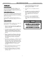
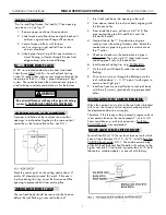
10. For floor return systems, the manufactured home
manufacturer or installer shall affix a prominent
warning where it is easily read when the closet door
is open.
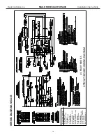
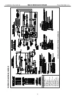
G18D Series Gas Furnace
INSTALLATION INSTRUCTIONS
HAZARD OF ASPHYXIATION
DO NOT COVER OR RESTRICT
FLOOR OPENING, or equivalent
!
WARNING
or other objects is
may be reduced
4


