Heat Controller DMH18DB-1 Service Manual Download Page 31

Service Manual  31

Air Purging and Evacuation

Air Purging and Evacuation

Air and moisture remaining in the refrigerant system have undesirable effects as indicated below.
1. Pressure in the system rises.
2. Operating current rises.
3. Cooling(or heating) efficiency drops.
4. Moisture in the refrigerant circuit may freeze and block capillary tubing.
5. Water may lead to corrosion of parts in the refrigeration system.
Therefore, the indoor/outdoor unit and connecting tube must be checked for leak tight, and vacuumed to remove
incondensible gas and moisture in the system.

Preparation

• Check that each tube(both liquid and gas side tubes)

between the indoor and outdoor units have been properly
connected and all wiring for the test run has been complet-
ed. Remove the service valve caps from both the gas and
the liquid side on the outdoor unit. Check that both the liq-
uid and the gas side service valves on the outdoor unit are
kept closed at this stage.

Leakage test

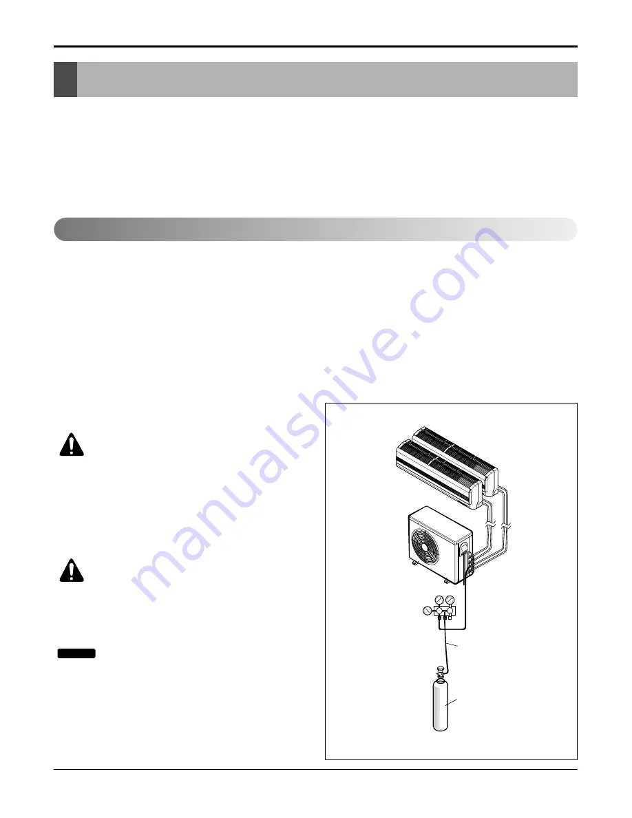
• Connect the manifold valve(with pressure gauges) and dry

nitrogen gas cylinder to this service port with charge
hoses.

CAUTION: Be sure to use a manifold
valve for leak testing.

The high side manifold valve must always
be kept closed.

• Pressurize the system to no more than 150 P.S.I.G.

with dry nitrogen gas and close the cylinder valve
when the gauge reading reached 150 P.S.I.G. Next,
test for leaks with liquid soap.

CAUTION: To avoid nitrogen entering the
refrigerant system in a liquid state, the top

of the cylinder must be higher than its bottom
when you pressurize the system. Usually, the
cylinder is used in a vertical standing position.

: Leakage test shoud be done for each

indoor unit connection set, separately.

1. Do a leakage test of all joints of the tubing(both

indoor and outdoor) and both gas and liquid side ser-
vice valves.
Bubbles indicate a leak. Be sure to wipe off the soap
with a clean cloth.

2. After the system is found to be free of leaks, relieve

the nitrogen pressure by loosening the charge hose
connector at the nitrogen cylinder. When the system
pressure is reduced to normal, disconnect the hose
from the cylinder.

NOTICE

Checking method

Charge hose

Nitrogen gas
cylinder(in vertical
standing position)

Indoor unit

Outdoor unit

Lo

Hi

Manifold valve

Pressure 
gauge

Summary of Contents for DMH18DB-1

Page 1: ...Wall Mounted Multi Split System Air Conditioning Heat Pump DMH18DB 1 Before servicing the unit read the safety precautions in this manual Only for authorized service personnel HEAT CONTROLLER INC...

Page 2: ...25 Connect the cable to the Outdoor unit 26 Connection method of the connecting cable Example 27 Connect the cable to the indoor unit 28 Checking the Drainage Forming the Pipings and Long Pipe Setting...

Page 3: ...ing Capacity is based on indoor temp 26 7 C 80 1 F DB 19 4 C 66 9 F WB outdoor temp 35 C 95 F DB 23 9 C 75 F WB 2 Heating Capacity is based on indoor temp 21 1 C 70 F DB 15 6 C 60 1 F WB outdoor temp...

Page 4: ...stallation Be sure not to do Be sure to follow the instruction Do not use a defective or under rated circuit breaker Use this appliance on a dedicated circuit There is risk of fire or electric shock F...

Page 5: ...ause injury accident or damage to the product Be sure the installation area does not deteriorate with age If the base collapses the air condi tioner could fall with it causing property damage product...

Page 6: ...m time to time when operating it together with a stove etc There is risk of fire or electric shock Turn the main power off when cleaning or maintaining the product There is risk of electric shock When...

Page 7: ...stall the drain hose to ensure that water is drained away properly A bad connection may cause water leakage Keep level even when installing the product To avoid vibration or water leak age Do not inst...

Page 8: ...plastic parts of the product Do not touch the metal parts of the product when removing the air filter They are very sharp There is risk of personal injury Do not step on or put anyting on the product...

Page 9: ...with clean water Do not use the remote if the batteries have leaked The chemicals in batteries could cause burns or other health hazards Use a firm stool or ladder when cleaning or maintaining the pro...

Page 10: ...10 Multi type Air Conditioner Dimensions Dimensions Indoor Unit Split Type Indoor Installation plate D H W W mm in 870 34 2 H mm in 270 10 6 D mm in 153 6 Model Dimension Split Type S4 9 kBtu h...

Page 11: ...W D L1 L2 L4 L3 H L7 L5 L6 W mm in 870 34 3 H mm in 655 25 8 D mm in 320 12 6 L1 mm in 370 14 6 L2 mm in 25 1 0 L3 mm in 775 30 5 L4 mm in 25 1 0 L5 mm in 546 21 5 L6 mm in 160 6 3 L7 mm in 160 6 3 UE...

Page 12: ...le A mm inch Gas Cycle A mm inch Liquid Cycle B mm inch Gas Cycle B mm inch High Pressure Gas mm inch Max Interunit Total Piping m ft Piping Length Main Piping m ft Total Branch Piping m ft Each Branc...

Page 13: ...r Unit Power and Transmission Interunit Cable No x mm2 Indoor Unit B DMH18DB 1 1 208 230 60 2 63 9000 2 63 9000 0 5 BLDC Cross Flow fan 15 1 7 247 1 Direct drive 2 15 20 870 270 153 34 2 10 6 6 7 15 4...

Page 14: ...trol Holder Installation plate Figure Figure Name Screw driver Electric Drill Measuring Tape Knife Hole Core Drill Spanner Torque wrench Ohmmeter Hexagonal wrench Ammeter Gas Leak Detector Thermometer...

Page 15: ...ricted 2 Ensure that the spaces indicated by arrows around front back and side of the unit 3 Do not place animals and plants in the path of the warm air 4 Take the air conditioner weight into account...

Page 16: ...h of each pipe A B Min length of each pipe A B Max Elevation between each indoor unit and out door unit h1 Max elevation between indoor units h2 B h2 h1 A B h1 CAUTION Capacity is based on standard le...

Page 17: ...easure the wall and mark the centerline It is also important to use caution concerning the location of the installation plate Routing of the wiring to power outlets is through the walls typically Dril...

Page 18: ...ss section of pipe tube 2 Put the end of the copper tube pipe in a downward direction as you remove burrs in order to avoid dropping burrs into the tubing Putting nut on Remove flare nuts attached to...

Page 19: ...h the piping hole Do not connect the cable to the indoor unit Make a small loop with the cable for easy connec tion later 3 Tape the tubing drain hose and the connecting cable Be sure that the drain h...

Page 20: ...the drain pipe Wrap the insulation material around the connecting portion 1 Overlap the connection pipe insulation material and the indoor unit pipe insulation material Bind them together with vinyl t...

Page 21: ...cer etc between the indoor unit and the installation plate and separate the bottom of the indoor unit from the wall Connecting the piping to the indoor unit and the drain hose to drain pipe 1 Align th...

Page 22: ...ng section Reroute the pipings and the drain hose across the back of the chassis Indoor unit installation 1 Remove the spacer 2 Ensure that the hooks are properly seated on the installation plate by m...

Page 23: ...t Be sure that both batteries are new Re attach the cover Slide it back into position REMOTE CONTROL PREPARATION OPTIONAL HOW TO MOUNT ONTO A WALL HOW TO INSERT BATTERIES Do not use rechargeable batte...

Page 24: ...orque wrench until the wrench clicks When tightening the flare nut with torque wrench ensure the direction for tightening follows the arrow on the wrench Liquid side piping Torque wrench B UNIT A UNIT...

Page 25: ...e to connect wires according to the wiring diagram Connect the wires firmly so that not to be pulled out easily Connect the wires according to color codes by referring to the wiring diagram WARNING Pr...

Page 26: ...C 167 F 3 Use outdoor and waterproof connection cable rated more than 300V for the connection between indoor and out door unit For example Type SJOW WARNING Be sure to comply with local codes while r...

Page 27: ...wiring to the terminals and fasten the wire tightly with the fixing screw of the terminal plate How to connect wiring to the terminals For strand wiring 1 Cut the wire end with a wire cutter or wire c...

Page 28: ...time delay fuse Main power source Model 18k 1 230 208V 20A Fuse or breaker Capacity Power source 1 Connect the wires to the terminals on the control board individually according to the outdoor unit c...

Page 29: ...hose of the indoor unit without any leakage and goes out the drain exit Drain piping 1 The drain hose should point downward for easy drain flow 2 Examples of incorrect drain piping Downward slope Do...

Page 30: ...ng drain hose and connecting cable from down to up 2 Secure the tapped piping along the exterior wall using saddle or equivalent In cases where the Outdoor unit is installed above the Indoor unit perf...

Page 31: ...rogen gas cylinder to this service port with charge hoses CAUTION Be sure to use a manifold valve for leak testing The high side manifold valve must always be kept closed Pressurize the system to no m...

Page 32: ...n the valve stem of liquid side valve counter clockwise to fully open the valve 2 Turn the valve stem of gas side valve counter clock wise to fully open the valve 3 Loosen the charge hose connected to...

Page 33: ...meter foot Example A 75ft line set is used for dual zone 25 additional ft X 0 22 ounces per foot add 5 5 ounces of R 410A Important Unit is critically charge If you are ever uncertain of the unit cha...

Page 34: ...the system refrigerant charge 1 Measure the pressure of one of the gas side service valves 2 Measure the temperature of the intake and discharge of air 3 Ensure the difference between the intake tempe...

Page 35: ...he remote control is received the intake air temperature is detected and the setting temp is automatically set according to the intake air temperature 26 C 78 8 F Intake Air Temp 25 C 77 F 24 C 75 2 F...

Page 36: ...he intake air temp at that moment as follows 24 C 75 2 F Intake Air Temp Fuzzy Operation for Cooling 21 C 69 8 F Intake Air Temp 24 C 75 2 F Fuzzy Operation for Dehumidification Intake Air Temp 21 C 6...

Page 37: ...the setting temp the compressor is turned on Compressor ON Temp Setting Temp Compressor OFF Temp Setting Temp 3 C 5 4 F At the beginning of Fuzzy mode operation the setting temperature is automatical...

Page 38: ...haos Swing or they are fixed to the desired direction While in Chaos Swing mode the angles of cooling and heating cycle operations are different Chaos Natural Wind Mode When the Chaos Natural Wind mod...

Page 39: ...n is switched from the forced operation position to the Auto Restarting position or the remote control position the forced operation is canceled and the appliance stops operating In the forced operati...

Page 40: ...e Setting Temp Indoor fan is delayed for 5 seconds at the starting Restarting is delayed for approx 3 minutes High Med Low Chaos Jet Cool Intermittent operation of fan at low speed The fan is switched...

Page 41: ...ng to heating heating to cooling Defrost Function After 45 min heating operation check the defrost condition and if outdoor pipe temp is below 5 C 23 F and released from deice operation in case outdoo...

Page 42: ...sed to stop or start louver movement and set the desired up down airflow direction ON OFF TIMER BUTTONS Used to set the time of starting and stopping operation TIME SETTING BUTTONS Used to adjust the...

Page 43: ...remove the Grille from the Chassis Set the up and down air discharge louver to open position horizontally by finger pressure Remove the securing screws To remove the Grille pull the lower left and ri...

Page 44: ...from the chassis carefully 3 To remove the Discharge Grille Unhook the discharge grille and pull the discharge grille out from the chassis carefully 4 To remove the Evaporator Remove 3 screws securin...

Page 45: ...Remove 2 securing screw Pull the motor cover out from the chassis carefully 6 To remove the Cross Flow Fan Loosen the screw securing the cross flow fan to the fan motor do not remove Lift up the right...

Page 46: ...46 Multi type Air Conditioner Schematic Diagram Schematic Diagram Electronic Control Device 1 Indoor Unit 1 Split Type...

Page 47: ...53 31 P37 34 35 36 P41 P40 33 32 P36 P35 RX C RX B TX C RX A TX B 14 13 P13 P12 P34 11 10 12 P10 P11 TX A CN LEV C CN LEV B DC 5V C52M 220 50V 2 3 1 2 3 1 5 4 5 4 IC03M 4 4 220 50V C51M 1 1 3 2 3 2 50...

Page 48: ...NF01J 1uF 1uF C03J 35V C10D 102M 561 2 C04D 35V 470UF 12uH L01D 1000UF 35V 220uF C05D 10V 220uF C03D DC 5V DC 15V IC04D C06D 50V 103 7805 C07D 50V 103 C02D 470uF 2K R02D 1 2W MT 15V C08D 103 50V L02D...

Page 49: ...Service Manual 49 1 Room Type Indoor Unit Wiring Diagram Schematic Diagram 2 Outdoor Unit...

Page 50: ...50 Multi type Air Conditioner Schematic Diagram 1 Indoor Unit MAIN P C B ASM 1 Split Type Components Locations TOP VIEW BOTTOM VIEW PCB 6870A90409B ASSY 6871A20771 6871A20782...

Page 51: ...Service Manual 51 Schematic Diagram 2 Display ASSEMBLY 1 Split Type 6871A20682A...

Page 52: ...52 Multi type Air Conditioner Schematic Diagram 3 Outdoor Unit 1 Component side...

Page 53: ...Service Manual 53 Schematic Diagram 2 Solder side...

Page 54: ...temperature CN TH2 Indoor Th2 Thermistor for indoor air temperature CN TH1 Indoor Th3 Thermistor for evaporating temperature CN TH1 Indoor Th4 Thermistor for evaporating temperature CN TH2 Indoor Th5...

Page 55: ...error code is different from Model Self diagnosis Function 00 No Error ON 01 Indoor Room Thermistor Error 1 time OFF 02 Indoor In Piping Error 2 times OFF 05 Communication Error between In and Out 5...

Page 56: ...1 The suction pressure is usually 4 5 6 0 kg cm2 G at normal condition 2 The temperature can be measured by attaching the thermometer to the low pressure tubing and wrap it with putty Temp difference...

Page 57: ...C230V 60Hz The voltage of main power The voltage applied to the unit The connecting method of Indoor Outdoor connecting cable each color The P W B Ass y Fuse Noise Filter Power Transformer IC01D IC02D...

Page 58: ...e Sleeping Mode the wind speed is set to the low speed as force Caused by the remote controller Caused by other parts except the remote controller When the mark is displayed in LCD screen replace batt...

Page 59: ...utdoor fan is stopped Check the related circuit of R01H 1K R02H 1K R03H 1K R04H 1K Micom pin No 74 75 76 77 Check the Indoor temperature sensor is disconnected or not about 10K at 25 C Check the Relay...

Page 60: ...t PWB Assy s Check the connecting condi tion and disconnection of connecting wires between Indoor and Outdoor unit Check the pattern and the condition of Indoor unit PWB Ass y Check the interference o...

Page 61: ...nnector Check the soldering condition on PWB of CN UP DOWN Connector Check the operating circuit of the Vertical Louver Confirm that there is DC 12V between pin RED of CN UP DOWN and GND Confirm that...

Page 62: ...gged Normal voltage 2 5Vdc at 25 C 77 F plugged Normal resistor 5K at 25 C 77 F Unplugged Normal voltage 2 5Vdc at 25 C 77 F plugged 10K 2 5Vdc Check the resistance voltage V Check Point 1 Unplug the...

Page 63: ...PCB is abnormal Transmission circuit of indoor PCB is abnormal Check Point 1 Check the input power AC 230V Outdoor Indoor 2 Check the communication wires are correctly connected Adjust the connection...

Page 64: ...point Normal condition code 51 Capacitor error Over Capacitor com bination Check the indoor unit capacity Check the combination table Check Point 1 Check the indoor unit capacity 2 Check the combinat...

Page 65: ...ered poorly Internal circuit error Normal resistor 10K at 25 C 77 F Unplugged Normal voltage 2 5Vdc at 25 C 77 F plugged Normal resistor 5K at 25 C 77 F Unplugged Normal voltage 2 5Vdc at 25 C 77 F pl...

Page 66: ...ap with cap Pumping down Closed Open Open Transfering clockwise counter clockwise connected manifold gauge Evacuation Open Open Open Servicing with charging cylinder Gas charging Open Open Open Servic...

Page 67: ...purging of the charge hose Open the Low handle valve on the gauge slightly to air purge from the hose 5 Set the liquid side valve to the closed position 6 Operate the air conditioner at the cooling cy...

Page 68: ...e has moved toward 76 cmHg vacuum of 4 mmHg or less 5 Close the Low handle of the gauge turn off the vacuum pump and confirm that the gauge needle does not move approximately 5 minutes after turning o...

Page 69: ...oner in the cooling cycle however one time is not suffi cient wait approximately 1 minute and then repeat the procedure pumping down pin 4 Immediately disconnect the charge hose from the gas side valv...

Page 70: ...Specifications and performance data subject to change without notice HEAT CONTROLLER INC 1900 WELLWORTH AVENUE JACKSON MICHIGAN 49203 THE QUALITY LEADER IN CONDITIONING AIR 05 15 07...

Reviews: