background image

Heat & Glo  •  Paloma  •  7031-220  Rev. P  •  10/08

9

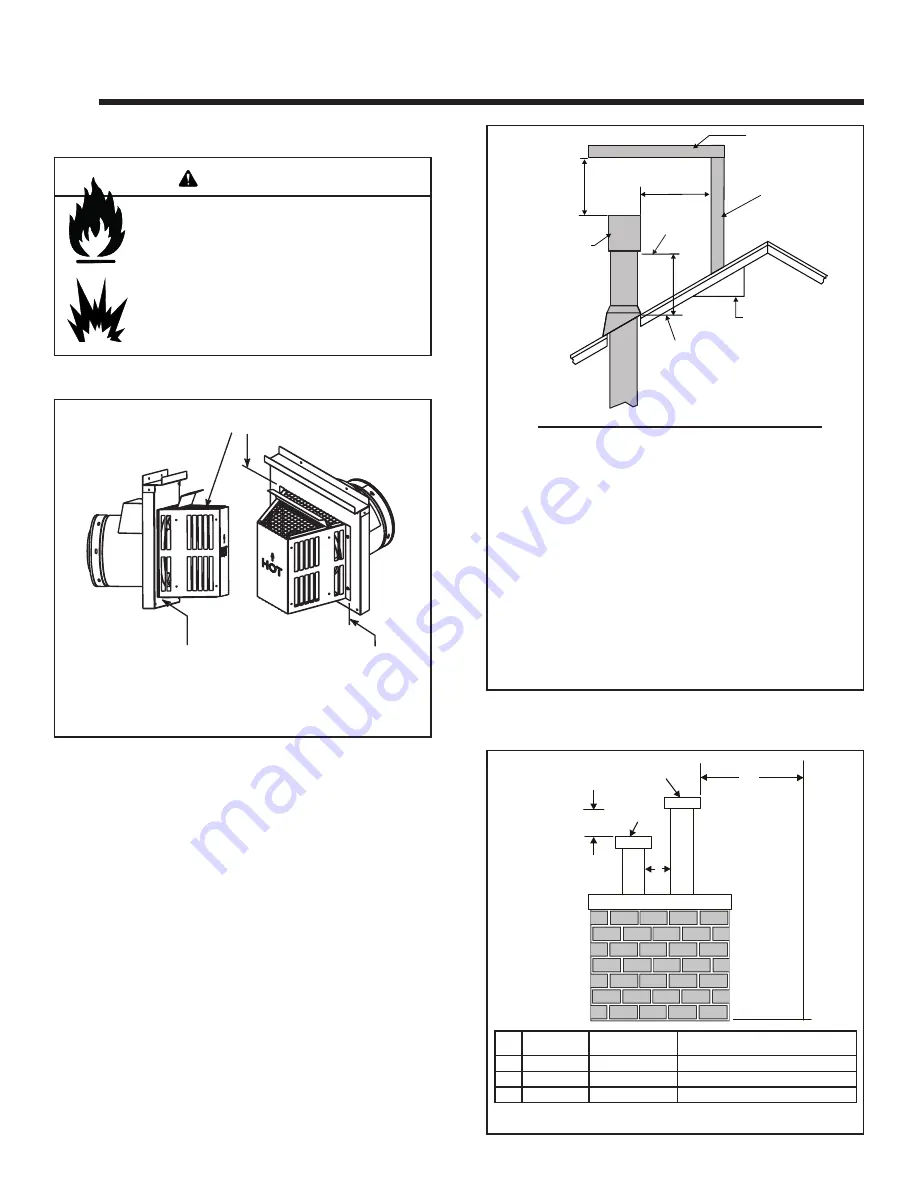
A.  Vent Termination Minimum Clearances

Fire Risk.

Explosion Risk.

Maintain vent clearance to combustibles as 
specifi ed.

•  Do not pack air space with insulation or other 

materials.

Failure to keep insulation or other materials 
away from vent pipe may cause fi re.

Figure 4.1

Termination Locations 


Measure horizontal clearances from this surface.

Measure vertical clearances from this surface.

(See Figure 4.4 for specifi c clearances)

WARNING

Roof Pitch 

H (Min.) Ft.

Flat to 6/12...........................................................1.0*
Over 6/12 to 7/12 .................................................1.25*
Over 7/12 to 8/12 .................................................1.5*
Over 8/12 to 9/12 .................................................2.0*
Over 9/12 to 10/12 ...............................................2.5
Over 10/12 to 11/12 .............................................3.25
Over 11/12 to 12/12 .............................................4.0
Over 12/12 to 14/12 .............................................5.0
Over 14/12 to 16/12 .............................................6.0
Over 16/12 to 18/12 .............................................7.0
Over 18/12 to 20/12 .............................................7.5
Over 20/12 to 21/12 .............................................8.0

Figure 4.2  Minimum height from roof to lowest discharge  
 opening

Figure 4.3  Multiple Vertical Termination

Figure 4.2 specifi es minimum vent heights for various 
pitched roofs.

* 3 foot minimum in snow regions

HORIZONTAL

OVERHANG

VERTICAL

WALL

GAS DIRECT VENT 
TERMINATION CAP

12

X

ROOF PITCH

IS  X/ 12

LOWEST

DISCHARGE

OPENING

2 FT.

MIN.

20 INCHES MIN.

H (MIN.) - MINIMUM HEIGHT FROM ROOF
TO LOWEST DISCHARGE OPENING

C

A

GAS

TERMINATION

B

GAS,  WOOD OR FUEL

OIL TERMINATION

Gas

Termination

Wood & Fuel Oil

Termination

Comments

A

6 in.

20 in. min.

Horizontal distance between terminations

B

20 in.

24 in. min.

Distance to perpendicular wall

C

18 in.

18 in. 

Vertical distance between terminations

Summary of Contents for PALOMA-BL

Page 1: ...r Installation in Mobile Homes CAN CSA Z240MH This appliance is only for use with the type s of gas indicated on the rating plate Installation and service of this appliance should be performed by qualified personnel Hearth Home Technologies suggests NFI certified or factory trained professionals or technicians supervised by an NFI certified professional Leave this manual with party responsible for...

Page 2: ...st be performed by a licensed plumber or gas fitter Manufactured by 7031 221 P 4 1 02 Canada Minimum Pipe 69 NG 71 L P Report No Rapport Numero 061 S 63 5 MODEL PALOMA VENTED GAS APPLIANCE NOT FOR USE WITH SOLID FUEL SERIAL NO Adivision of Hearth Home Technologies 20802 Kensington Blvd Lakeville MN 55044 www heatnglo com 007 Tested and Listed by Beaverton Oregon USA OMNI Test Laboratories Inc C Se...

Page 3: ...essures 28 D Gas Connection 29 7 Electrical Information A Recommendation for Wire 30 B Connecting to the Appliance 30 C IntelliFire Ignition System Wiring 30 D Loss of Power and Battery Backup Usage 31 E Wall Switch Installation for Fan Optional 32 8 Appliance Setup A Remove Shipping Materials 33 B Unbolting Appliance from the Pallet 33 C Leveling and Lagging Down the Appliance 34 D Accessories 34...

Page 4: ...titudes A Appliance Certification E Non Combustible Materials Specification Material which will not ignite and burn Such materials are those consisting entirely of steel iron brick tile concrete slate glass or plasters or any combination thereof Materials that are reported as passing ASTM E 136 Standard Test Method for Behavior of Materials in a Vertical Tube Furnace at 750ºC shall be considered n...

Page 5: ...ng appliance or equipment The sign shall read in print size no less than one half 1 2 inch in size GAS VENT DIRECTLY BELOW KEEP CLEAR OF ALL OB STRUCTIONS Inspection The state or local gas inspector of the side wall horizon tally vented gas fueled equipment shall not approve the installation unless upon inspection the inspector ob serves carbon monoxide detectors and signage installed in accordanc...

Page 6: ...ly remove the appliance and components from the packaging Remove door and set aside on protective surface See page 44 Remove log set and component pack from firebox Report to your dealer any parts damaged in shipment particularly the condition of the glass Read all of the instructions before starting the insta llation Follow these instructions carefully during the installation to ensure maximum sa...

Page 7: ...s diagrams are not drawn to scale Actual installation may vary due to individual design preference Fire Risk Provide adequate clearance Around air openings To combustibles For service access Locate appliance away from traffic areas A Selecting Appliance Location When selecting a location for your appliance it is important to consider the required clearances to walls see figure 3 1 Figure 3 1 NOTE ...

Page 8: ...er for maximum temperature allowed on flooring surfaces It is permissible to place the appliance on carpet Some carpet materials may be sensitive to radiant heat from the appliance causing discoloration or odor CAUTION Fire Risk Locate and install appliance to all clearance specifications in manual WARNING WARNING Fire Risk Odor Risk Tipping Risk Install gas stove on a stable level platform floor ...

Page 9: ...2 3 25 Over 11 12 to 12 12 4 0 Over 12 12 to 14 12 5 0 Over 14 12 to 16 12 6 0 Over 16 12 to 18 12 7 0 Over 18 12 to 20 12 7 5 Over 20 12 to 21 12 8 0 Figure 4 2 Minimum height from roof to lowest discharge opening Figure 4 3 Multiple Vertical Termination Figure 4 2 specifies minimum vent heights for various pitched roofs 3 foot minimum in snow regions HORIZONTAL OVERHANG VERTICAL WALL GAS DIRECT ...

Page 10: ... an overhang are permitted with the dimensions specified for vinyl or non vinyl siding and soffits 1 There must be 3 feet minimum between termination caps 2 All mechanical air intakes within 10 feet of a termination cap must be a minimum of 3 feet below the termination cap 3 All gravity air intakes within 3 feet of a termination cap must be a minimum of 1 foot below the termination cap See Note 1 ...

Page 11: ... outer pipe The inner pipe carries the appliance exhaust out of the system and the outer pipe brings fresh combustion air into the appliance A round support box wall thimble or heat shield is required when the venting passes through a combus tible wall A support box or ceiling firestop is required when the venting passes through a ceiling Roof flashing and a storm collar are required when venting ...

Page 12: ...4 m the horizontal run to the outer wall flange must not exceed 9 ft 3 m 4 Each 90 elbow is equivalent to 3 ft 914 mm of vent pipe and each 45 elbow is equivalent to 1 ft 305 mm of vent pipe and must be subtracted from vent pipe run A single vertical to horizontal 90 elbow is already calculated into the allowable 15 ft 5 m run Each additional 90 elbow reduces the maximum horizontal distance by 3 f...

Page 13: ...un supports per installation instructions Connect vent sections per installation instructions Maintain all clearances to combustibles Do NOT allow vent to sag below connection point to appliance Maintain specified slope if required Improper support may allow vent to sag or separate WARNING FEMALE LOCKING LUGS MALE LOCKING 1 Determine the desired location of the appliance Check to ensure that wall ...

Page 14: ...between it and the wall attach termination cap to the exterior wall with the four wood screws provided The arrow on the vent cap should be pointing up Figure 5 6 Figure 5 6 Figure 5 7 10 If you are installing termination cap HHW2 the pipe will be off center on flashing Ensure that proper clearances to combustible materials are maintained If you are using an approved termination cap other than HHW2...

Page 15: ...BLE COVER WALL THIMBLE VINYL SIDING STANDOFF WITH SIDING BENEATH REMOVED SCREWS BOLT HORIZONTAL TOP TO VINYL STANDOFF SCREWS APPLY SEALANT TO ALL FOUR SIDES VINYL SIDING Figure 5 8 Note The attachment from the vent pipe to the vent termination cap must be sealed with silicone Termination caps shall not be recessed into a wall or siding Fire Risk Exhaust Fumes Risk Impaired Performance of Appliance...

Page 16: ...b bob down from the ceiling to the position of the appliance flue exit and mark the location where the vent will penetrate the ceiling Drill a small hole at this point Next drop a plumb bob from the roof to the hole previously drilled in the ceiling and mark the spot where the vent will penetrate the roof Determine if ceiling joists roof rafters or other framing will obstruct the venting system Yo...

Page 17: ...ng material overlaps the top edge of the flashing as shown in Figure 5 14 Verify that the chimney is the required height above the roof See roof pitch table Figure 4 3 on page 9 3 To install the round support box wall thimble cover in a flat ceiling cut a 10 in 254 mm square hole in the ceiling centered on the hole drilled in Step 2 Frame the hole as shown in Figure 5 13 FRAMING 1 1 2 in 38 mm LON...

Page 18: ... be framed to 10 in x 10 in 254 mm x 254 mm inside dimensions in the same manner as shown in Figure 5 13 Fire Risk Explosion Risk Any occupied areas above the first floor including closets and storage spaces which the vertical vent passed through must be enclosed The enclosure may be framed and sheetrocked with standard construction materials however refer to these installation instructions for th...

Page 19: ...edges of the support box to make a seal between it and the roof Clean out any combustible material from inside the support box 5 Assemble the desired lengths of pipe and elbows necessary to reach from the appliance up through the round support box Ensure that all pipe and elbow connections are in their fully twist locked position Assemble as instructed 6 Place the support clamp provided with the s...

Page 20: ...sheet metal screws 7 The connection between the appliance and the retro connector may be completed with sections of direct vent pipe 1 Remove existing chimney cap 2 Measure the distance from the top of the chimney to the bottom of the ceiling support box add 3 in 76 mm to this measurement and cut a section of 4 in 101 mm flex pipe to that length the flex should be fully extended 3 Connect the end ...

Page 21: ...ON TO TERMINATION USING A SMOKE SHELF OR A DAMPER SEAL SHOULD BE 6 IN 152 mm BELOW END OF 4 FT 1 m AIR INTAKE SECTION THIS SECTION OF THE CHIMNEY MUST BE SEALED CO AXIAL TO CO LINEAR CONNECTOR PART 923GCL ALCOVE CLEARANCE TO COMBUSTIBLES MUST BE MAINTAINED Figure 5 24 NOTE In the Commonwealth of Massachusetts the word damper shall be replaced with the words flue restrictor CO AXIAL TO CO LINEAR CO...

Page 22: ... to this length extended to its nominal length Be sure to leave 2 3 in 51 76 mm of flex above the existing chimney to allow for connection to the termination kit 5 Connect the flex liner to the top adapter using three sheet metal screws Figure 5 21 page 20 6 Feed the flex liner through the flashing into the chimney Carefully feed the flex liner down the chimney to the bottom and out the opening in...

Page 23: ...VER 10 Slide wall thimble cover over retro connector and secure with masonry bolts Figure 5 30 If you have a framed wall in front of the masonry use wood screws to mount wall thimble cover to framed wall over retro connector and 10 in 254 mm square framed opening Figure 5 25 page 22 If needed add a section of direct vent pipe to the retro connector in order to extend through the opening in the wal...

Page 24: ...nd bent into a half circle before attaching it to the trim ring Bend the heat shield as shown Figure 5 33 Attach the heat shield to the trim ring with the four screws provided Screws go through the heat shield and into the brackets on the trim ring Figure 5 34 When installing the trim ring heat shield assembly make sure the trim ring is centered in the hole and that the shield is above the pipe Th...

Page 25: ...ER TOP HALF OF PIPE Figure 5 35 FIG B 45 DEGREE ELBOW 90 ELBOW PIPE LENGTH PIPE LENGTH CENTER LINE TRIM RING HTI VENT HHW2 PART 841 0670 RECOMMENDED FOR OPTIMUM PERFORMANCE PLACE MARK WHERE PROTRUDES THROUGH EXTERIOR WALL TO CUT OFF EXCESS USE HEAT SHIELD WALL THIMBLE 45 ELBOW 5 IN 127 MM CLEARANCE FROM APPLIANCE CORNER 5 IN 127 MM CLEARANCE FROM APPLIANCE CORNER TO COMBUSTIBLE WALL HEAT SHIELD OV...

Page 26: ...ified technician using Hearth Home Technologies specified and approved parts 6 6 Gas Information Fire Risk Explosion Risk If the information in these instructions is not followed exactly a fire explosion or produc tion of carbon monoxide may result causing property damage personal injury or loss of life The qualified service agency is respon sible for the proper installation of this kit The instal...

Page 27: ...that the shutter setting is fully open Reattach pilot to pilot shield to burner see Figure 6 5 Retighten the screw 14 Reinstall the bottom plate and valve assembly into the appliance Reinstall the six hold down screws 15 Reconnect the inlet gas line to the valve assembly and turn on the gas line valve Check the incoming line for leaks 16 Reconnect the electrical power supply 17 Reconnect the orang...

Page 28: ...nformation in these instructions is not followed exactly a fire explosion or production of carbon monoxide may result causing property damage personal injury or loss of life The qualified service agency is responsible for the proper installation of this conversion kit The installation is not proper and complete until the operation of the converted appliance is checked as specified in the manufactu...

Page 29: ...as Leak Risk Support control when attaching pipe to prevent bending gas line Note The gap between supply piping and gas access hole may be caulked with high temperature caulk or stuffed with non combustible unfaced insulation to prevent cold air infiltration WARNING Fire hazard Do NOT change the valve settings This valve has been preset at the factory Changing valve settings may result in fire haz...

Page 30: ...9 The thermostat should be mounted on an inside wall and not in direct line with the appliance convection air 10 If the thermostat is located too close to the appli ance you may need to set the temperature setting slightly higher to maintain the desired temperature in your home Wire Size Max Length 16 gauge 65 feet 18 gauge 40 feet 20 gauge 25 feet 22 gauge 18 feet A Recommendation for Wire See Fi...

Page 31: ...1 Disconnect the power supply 2 Remove the front door assembly and lower access panel 3 Place two D cell batteries into the battery holder Figure 7 3 4 Turn on appliance and verify it is operational 5 Replace lower access panel and front door assembly CAUTION Label all wires prior to disconnection when servicing controls Wiring errors can cause improper and dangerous operation Verify proper operat...

Page 32: ...of 14 3 with ground wire At the switch box connect the black hot wire and red switch leg wire to the wall switch as shown At the appliance connect the black hot white neutral and green ground wires to the junction box as shown Add a 1 4 inch insulated female connector to the red switch leg wire route it through the knockout in the face of the junction box and connect to the top fan switch connecto...

Page 33: ...power cord are shipped inside back panel To access the gas line and power cord remove the top plate from the appliance Remove and retain the two Allen head screws that hold the back panel in place Refer to Figure 8 6 page 33 Using the black grommet located in the component bag slide it into the bottom of the back panel and feed the power cord through the grommet as shown in Figure 8 2 8 8 Applianc...

Page 34: ... high pressure laminate flooring applied directly over the sub flooring material Figure 8 5 Securing holes Lag bolt hole Place the lag bolt from the component bag in the center hole in the bottom plate lagging clearance hole The appliance must be lagged down securely to prevent tip ping forward Figure 8 7 D Accessories Install approved accessories per instructions included with accessories See Ser...

Page 35: ...t configura tion with no vertical rise a Snorkel Kit must be used Figure 8 8 3 Remove and retain the Allen head screws that hold the solid back panel in place Figure 8 9 Remove and discard the solid back panel 4 Remove the four screws from the DV adapter collar Figure 8 10 Set aside DV adapter collar and screws 5 Remove the inner extension starter collar Shown in Figure 8 10 and set aside PILOT AS...

Page 36: ...The vent restrictor plate must be installed before installing the baffle On the top of inside firebox for top vent on back of firebox for rear vent loosen the three screws out about 1 8 in Place the vent restrictor plate over the the screws and slide into locking position Retighten the screws See Figure 8 15 Figure 8 14 For vertical venting above 6 ft a vent restrictor is required After installing...

Page 37: ...ile still breakable the logs do not become fragile until after the appliance is burned and they have cured After curing any handling must be done with care as breakage can easily occur Figure 8 18 Figure 8 20 PILOT ASSEMBLY PILOT ASSEMBLY IGNITER SHIELD IGNITER SHIELD Note Logs have been designed to work specifically with the burner of this appliance Exact placement will ensure proper operation of...

Page 38: ...fore starting installation and to follow these instructions carefully during installation to assure maximum benefit from and safe operation of the blower This blower is carefully engineered and must be installed only as specified If you modify it or any of its components you may cause a fire hazard and will void the WARRANTY In addition such action may void the coverage provided by the owner s hom...

Page 39: ...See Figure 8 23 Figure 8 24 Figure 8 25 Feed the blue wire and other black wire from the variable speed control behind the gas valve assembly Insert the wires into the slots indicated Figure 8 26 Locate the machine screw underneath the firebox on the right side Position the temperature sensor switch bracket assembly over the machine screw and attach with the wing nut Finger tighten See Figure 8 26...

Page 40: ...the FAN outlet on the junction box Refer to Figure 8 29 on the next page Push excess wires neatly towards the rear of the appliance Slide the blower into the bracket as indicated Ensure the blower is pushed back into the bracket to allow the replacement of the lower access door The magnet strips located on the blower feet are designed to hold the blower in place See Figure 8 28 Figure 8 28 Attach ...

Page 41: ...Rev P 10 08 41 Figure 8 30 Blower Wiring Diagram BLUE VARIABLE SPEED SWITCH TEMPERATURE SENSOR SWITCH JUNCTION BOX Shock hazard Replace damaged wire with type 105º C rated wire Wire must have high temperature insulation WARNING ...

Page 42: ...Remote receiver Remove the top plate from the appliance Remove the Allen head screws attaching the back panel to the appli ance Retain screws Remove the front glass door assembly and the lower access door Using two wire ties from the appliance component bag mount the remote receiver to the rear of the control panel Feed the red and orange wires to the front of the appli ance Remove the optional bl...

Page 43: ...See Figure 8 33 Install a manometer into the pressure tap Plug the remote receiver into the 110 120 VAC power supply Light the appliance as directed in Section 9 of this manual Set the manifold pressure on the gas valve by rotating the flame control solenoid Adjust until the reading on the manometer is 3 5 in W C for natural gas or 10 in W C for LP Tighten the jam nut to the face of the variable r...

Page 44: ...7 Complete Assembly CAP AND BARREL FASTENER SYSTEM Nylon washer on back and front of glass Screw Finishing Cap Protective barrel sleeve through hole in the glass Back side of front door Figure 8 35 Position the four flat 1 4 in 6 mm spacer washers on the front door so that the four mounting screws pass through them Position the glass over the front door Install the four protective barrels into the...

Page 45: ...ow of combustion and ventilation air is not obstructed front grilles and vent caps Glass door must be in place when appliance is operating Risk of Combustion Fumes Fire Do NOT operate appliance with glass door removed Open viewing glass for servicing only Glass door MUST be in place and sealed before operating appliance Only use glass door certified for use with appliance Glass replacement should ...

Page 46: ...ry to light any appliance Do not touch any electric switch do not use any phone in your building DO NOT CONNECT 110 VAC TO THE CONTROL VALVE Improper installation adjustment al teration service or maintenance can cause injury or property damage Re fer to the owner s information manual provided with this appliance This appliance needs fresh air for safe operation and must be installed so there are ...

Page 47: ...ttended Unplug or remove batteries from remote control if absent or if appliance will not be used for an extended period of time Property damage possible from elevated temperatures CAUTION Fire Hazard Keep combustible materials gasoline and other flammable vapors and liquids clear of appliance Do NOT store flammable materials in the appliance s vicinity Do NOT use gasoline lantern fuel kerosene ch...

Page 48: ...module Check voltage of transformer under load at spade connection on module with ON OFF switch in ON position Acceptable readings of a good transformer are between 3 2 and 2 8 volts AC b A shorted or loose connection in wir ing configuration or wiring harness Remove and reinstall the wiring harness that plugs into module Verify there is a tight fit Verify pilot assembly wiring to module Remove an...

Page 49: ...set at lowest range e Faulty module Turn ON OFF rocker switch or wall switch to OFF posi tion Remove ignitor wire I from module Place ON OFF Rocker switch or wall switch in ON position Hold ground wire about 3 16 inch away from I terminal on module If there is no spark at I terminal module must be replaced If there is a spark at I terminal module is fine Inspect pilot assembly for shorted sparker ...

Page 50: ...s after initial 3 4 hours operation Longer operation without cleaning glass may cause a permanent white film on glass CAUTION When cleaning glass door Avoid striking scratching or slamming glass Do NOT use abrasive cleaners Use a hard water deposit glass cleaner on white film Do NOT clean glass when hot Turn off appliance after 3 4 hours of operation and ALLOW TO COOL Remove and clean glass assemb...

Page 51: ...orrosion or perforation Sand and repaint as necessary 2 Replace appliance if firebox has been perforated Burner Ignition and Operation 1 Verify burner is properly secured and aligned with pilot or igniter 2 Clean off burner top inspect for plugged ports corrosion or deterioration Replace burner if necessary 3 Replace ember materials with new dime size and shape pieces Do not block ports or obstruc...

Page 52: ...Inches Millimeter Location Inches Millimeter A 18 7 8 479 F 7 1 8 181 B 40 3 4 1035 G 30 762 C 40 3 8 1025 H 28 7 8 733 D 15 7 8 403 I 33 3 4 857 E 3 76 12 12 Reference Materials A Appliance Dimension Diagram Without Stone Surround Dimensions are actual appliance dimensions Use for reference only For framing dimensions and clearances refer to Section 3 ...

Page 53: ... 3 8 in 9 53 mm hearth pad F G C E B A Hearth Pad D Figure 12 2 Appliance Dimensions with Stone Surround Location Inches Millimeter Location Inches Millimeter A 29 5 8 753 E 16 7 8 428 B 24 3 8 620 F 34 5 8 879 C 30 1 4 768 G 44 5 16 1126 D 3 1 4 83 B Appliance Dimension Diagram With Stone Surround ...

Page 54: ... mm 7 1 4 in 184 mm 5 1 4 in 133 mm 25 1 4 in 641 mm 37 1 4 in 946 mm 49 1 4 in 1251 mm 13 1 4 in 337 mm 13 1 4 in 337 mm 6 5 8 in 168 mm 6 5 8 in 168 mm 6 5 8 in 168 mm 6 5 8 in 168 mm SLP45 SLP90 SLP12 SLP6 SLP4 SLP24 SLP36 SLP48 SLP12A SLP6A 6 5 8 in 168 mm 6 5 8 in 168 mm 6 9 16 in 167 mm 6 5 8 in 168 mm 6 5 8 in 168 mm 6 5 8 in 168 mm 6 5 8 in 168 mm 6 9 16 in 167 mm 6 9 16 in 167 mm 6 9 16 i...

Page 55: ...Firestop SLP WS Wall Firestop SLP HVS Pipe Support Hanger 950 Vinyl Protector Kit SL Pipe DRC RADIUS Decorative Radius Cover HTI DV WT Wall Thimble RF4 8 Roof Flashing TERMINATION KITS SLP TRAP2 Trapezoid Termination Kit SLP TVHW Vertical Termination Cap High Wind SLP SK BK Horizontal Termination Kit includes 904B 930D SLK 01TRD SLK SNKD Snorkel Kit LINK STOVE Adapter Kit includes 30 ft of 4 inch ...

Page 56: ...v P 10 08 56 Beginning Manufacturing Date July 2005 Ending Manufacturing Date ______ E Service Parts Service Parts Diagram PALOMA Part number list on following page 1 2 3 4 5 6 7 8 9 10 11 12 13 14 15 16 17 18 19 Log Set Assembly ...

Page 57: ...15 Post Sept 2007 2123 005 Latch Assembly Lower Pre Sept 2007 7031 041 Y Post Sept 2007 386 122A Y Latch Assembly Upper 7003 006 Y Baffle Support 7031 437 7 Side Assembly Left 7031 024 8 Exhaust Baffle 7031 219 9 Front Door Assembly Bronze 2123 028 Green 2123 029 Gray 2123 016 10 Access Door Assembly 7031 023 11 Flame Control Knob 571 531 Y 12 Firebox Bottom Assembly 7031 012 13 Bottom Plate Assem...

Page 58: ...ue Restrictor Plate 7031 222 Conversion Kit NG NGK PALOMA Y Conversion Kit LP LPK PALOMA Y Pilot Orifice NG 593 528 Y Pilot Orifice LP 593 527 Y Regulator NG NGK DXV Y Regulator LP LPK DXV Y Blower with Rheostat GFK 160A Remote Control RCT MLT HNG Wall Thermostat WH STAT Wall Switch Kit Off white WSK 21 Wall Switch Kit White WSK 21 W Rear Vent Conversion Kit Pre May 2008 SRV PAL TR Post May 2008 P...

Page 59: ...ESCRIPTION COMMENTS PART NUMBER 1 Burner Assembly Hybrid 7031 032 Y 2 Pilot Shield 7031 234 3 Pilot Assembly NG 2090 012 Y Pilot Assembly LP 2090 013 Y 4 Burner Support 7031 265 5 Firebox Bottom Plate Pre Apr 2008 7031 122 Post Apr 2008 2123 123 6 Gasket Firebox Bottom 7031 202 7 Valve Bracket Pre Apr 2008 7031 128 Post Apr 2008 2111 186 8 Valve NG 750 500 Y Valve LP 750 501 Y 9 Flex Ball Valve As...

Page 60: ...nder this warranty is limited to the purchase price of the product In no event shall HHT be liable for any incidental or consequential damages caused by defects in the product Adjustments regular maintenance cleaning and temporary repairs or the failure to duplicate the problem in the home is not covered under this warranty Page 1 of 2 4021 645A 09 01 08 Warranty Period HHT Manufactured Appliances...

Page 61: ...d approved by HHT in writing This warranty does not apply to non HHT venting components hearth components or other accessories used in conjunction with the installation of this product This warranty is void if the appliance has been over fired or operated in atmospheres contaminated by chlorine fluorine or other damaging chemicals the appliance is subject to prolonged periods of dampness or conden...

Page 62: ..._________________________________________________ ________________________________________________________________________________ Printed in U S A Copyright 2008 This product may be covered by one or more of the following patents United States 4593510 4686807 4766876 4793322 4811534 5000162 5016609 5076254 5113843 5191877 5218953 5263471 5328356 5341794 5347983 5429495 5452708 5542407 5601073 561...

Reviews: