background image

 WARNING! 

Risk of Fire! 

  •  Maintain clearances. 

  •  Use only non-combustible material below standoffs, 

material such as cement board is acceptable.

  •  Framing or fi nishing material used on the front of 

the fi replace closer than the minimums listed, must 

be constructed entirely of non-combustible materi-

als (i.e., steel studs, concrete board, etc.).

 WARNING! 

Risk of Fire!

  Hearth & Home Technologies is not responsible for 

discoloration, cracking or other material failures of 

fi nishing materials due to heat exposure or smoke.

  •  Choose fi nishing materials carefully. 

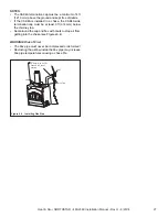
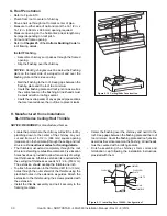
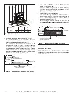
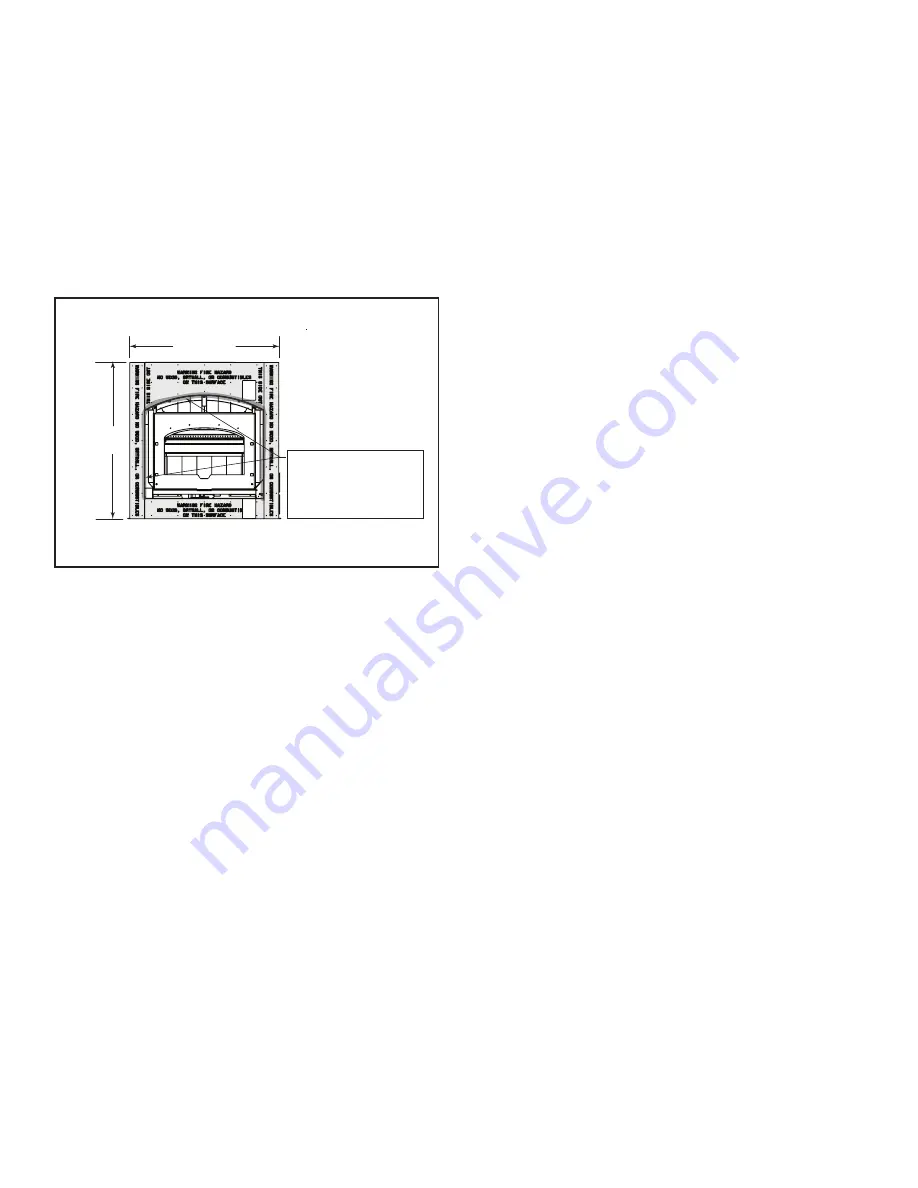
Seal inside perimeter of 

fireplace finished opening 

with non-combustible 

grout to prevent risk of fire 

and cold air infiltration.

45-1/2 in.

(1156 mm)

45-1/2 in.

(1156 mm

)

NON-COMBUSTIBLE ZONE

Figure 7.7

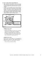
E. Non-Combustible Sealant Material

•  After  completing  the  installation  of  non-combustible 

material in the required non-combustible zone and the 

non-combustible fi nishing material over that, remove the 

template.

•  A bead of non-combustible sealant (or Super Calstick) 

must be used to close off any gaps at the top and sides 

between  the  fireplace  and  non-combustible  facing 

(Figure 7.7) to prevent cold air leaks and the risk of fi re. 

Large gaps can be bridged with fi berglass rope gasket.

•   When installation of the decorative material is complete, 

replace/install the fascia and fi replace doors.

37

Heat & Glo • NORTHSTAR • 480-2360 Installation Manual • Rev H • 8/20/14

Summary of Contents for NORTHSTAR-BK

Page 1: ...rt children and adults to hazards of high temperatures High temperatures may ignite clothing or other flammable materials Keep clothing furniture draperies and other flammable materials away INSTALLER Leave this manual with party responsible for use and operation OWNER Retain this manual for future reference NORTHSTAR BK NORTHSTAR GT NORTHSTAR NT NOTICE DO NOT discard this manual DO NOT store or u...

Page 2: ...rances 12 C Construct the Chase 13 D Frame the Fireplace 14 E Secure and Level the Fireplace 14 F Protective Metal Hearth Strips 15 G Facing Material 15 H Outside Air Kit 16 I Heat Zone Kit Optional 18 4 Electrical Wiring 5 Chimney and Termination Requirements A Chimney Requirements 22 B Offsets Returns 23 C Termination Requirements 24 6 Chimney Installation A Typical Chimney System 25 B Assemble ...

Page 3: ...installed in non combustible areas Verified all clearances meet installation manual requirements Mantels and wall projections comply with installation manual requirements Protective hearth strips and hearth extension installed per manual requirements Fireplace Setup Section 8 Pg 38 All packaging and protective materials removed Firebrick baffle and ceramic blanket installed correctly Facia and doo...

Page 4: ...nstallation Codes in Canada Warning Risk of Fire Hearth Home Technologies disclaims any responsibility for and the warranty and agen cy listing will be voided by the following actions DO NOT install or operate damaged fireplace modify fireplace install other than as instructed by Hearth Home Technologies operate the fireplace without fully assembling all components overfire install any gas log set...

Page 5: ...upter protection in compliance with the applicable electrical codes when it is installed in damp locations WARNING Improper installation adjustment alteration service or maintenance can cause injury or property dam age D Combustible Materials Materials made of or surfaced with any of the following materials Wood Compressed paper Plant fibers Plastic Plywood OSB Sheet rock drywall Any material that...

Page 6: ...enetrates roof preferably without affecting roof rafters Storm Collar Offset Return with hanger straps Attic insulation shield must be used here to keep insulation away from chimney if attic is insulated Framing headed off in ceiling joists Mantel Decorative facing and trim Factory built fireplace Chimney system Combustible framing header on top of V shaped standoffs spacers Hearth extension Prote...

Page 7: ...o installation Installation MUST comply with local regional state and national codes and regulations Consult insurance carrier local building inspector fire officials or authorities having jurisdiction over restrictions installation inspection and permits 1 Selecting Fireplace Locations This fireplace may be used as a room divider installed along a wall across a corner or used in an exterior chase...

Page 8: ...vel Roofs Windward Leeward Recommended Location Above peak Recommended Insulated exterior chase in cooler climates Recommended Location Above peak Inside heated space Location NOT recommended Too close to tree Below adjacent structure Lower roof line Avoid outside wall Marginal Location Wind loading possible Figure 2 3 Recommended Chimney Locations Install the outside air kit with the intake facin...

Page 9: ...oors are shipped in separate packages Report to your dealer any parts damaged in shipment Read all the instructions before starting the installation Follow these instructions carefully during the installation to ensure maximum safety and benefit E Fireplace System Requirements The fireplace system requirements consist of the follow ing Fireplace Firebrick included with fireplace Door included with...

Page 10: ...ectrical Access right side of fireplace 283 mm 587 mm 25 mm 89 mm 1111 mm 1022 mm 791 mm 149 mm 743 mm 940 mm 1016 mm 1066 mm 422 mm 305 mm 25 mm 248 mm 175 mm Figure 3 1 Fireplace Dimensions 10 Heat Glo NORTHSTAR 480 2360 Installation Manual Rev H 8 20 14 ...

Page 11: ...gure 3 2 Clearances to Combustible Materials 2 in 51 mm min Attic Insulation Shield Ceiling Firestop ceiling roof attic ceiling Ceiling Firestop Offset Return with hanger straps Storm Collar Roof Flashing 2 in 51 mm min 2 in min 51 mm Must have 2 in 51 mm minimum clearance to header 2 in 51 mm min 2 in 51 mm min 2 in 51 mm min 1 in 25mm to side of appliance except at nailing flanges where it is 1 ...

Page 12: ...o backwall 1 2 in 13 mm Fireplace to sidewall 1 in 25 mm Duct boots to framing 0 in 0 mm Top standoffs to header 0 in 0 mm Door opening to sidewall 22 7 8 in 581 mm EXPOSED SURFACES Faceplate to sidewall 16 in 406 mm Heat zone air grills to ceiling 12 in 305 mm MANTEL Non combustible mantel Non combustible framing materials above the fireplace to ceiling 46 in 1168 mm Combustible mantel Combustibl...

Page 13: ...ld be insulated Figure 3 5 Chase Constructions 1 Fireplace and chimney enclosed in an exterior chase 2 Chimney offset through exterior wall and enclosed in chase 3 Chase constructed on roof The chase is constructed using framing materials much the same as the walls in your home A variety of siding materials may be used including brick stone veneer brick or standard siding materials In constructing...

Page 14: ...bove the level of the top standoffs No recess above standoffs The finished cavity depth must be no less than 24 in 610 mm from the finished backwall to the outside of front wall framing Framing must extend straight up all the way to the ceiling Caution Risk of Cuts Abrasions Wear protective gloves and safety glasses during installation Sheet metal edges are sharp Warning Risk of Fire Prevent conta...

Page 15: ... be installed Hearth extensions MUST be installed exactly as specified WARNING Risk of Fire Follow these instructions exactly Facing materials must be installed properly to prevent fire No materials may be substituted without authorization by Hearth Home Technologies G Facing Material TOOLS NEEDED Powered drill with 2 Phillips head bit caulking gun Only non combustible materials supplied with fire...

Page 16: ...e the pipe to prevent frost condensation Use the supplied outside air inlet hood Seal between the wall and the pipe with silicone to prevent moisture penetration and air leaks Seal between the outside air inlet hood and the house with silicone to prevent air infiltration Caution Risk of Cuts Abrasions Wear protective gloves and safety glasses during installation Sheet metal edges are sharp Caution...

Page 17: ...mination cap NO UL181 Listed Class 0 or Class 1 metal flex or rigid duct Figure 3 11 Outside Air Installation Figure 3 12 Outside Air Termination Cap supplied with fireplace UL 181 Listed Class 0 or Class 1 metal flex or rigid duct Open Close Knob for outside air CLOSE OPEN 17 Heat Glo NORTHSTAR 480 2360 Installation Manual Rev H 8 20 14 ...

Page 18: ...kit conveys warm air from the fireplace through air duct s to remote locations in the same room or other rooms of the building You may install 1 or 2 Heat Zone kits on the fireplace Installation of this kit MUST be performed by a qualified service technician If any parts are missing or damaged contact your local dealer before starting installation DO NOT install a dam aged kit This kit is tested a...

Page 19: ...ssembly Cut a 7 5 8 in x 13 5 8 in 143 mm x 346 mm hole between framing members wall studs or floor joists The brackets can be rotated 180 and mounted to the back side of the 2 x 4 if necessary See Figure 3 16 NOTICE The fan and electrical connections must be accessible for servicing per local code requirements NOTICE If the fan housing is installed in a 2 x 4 wall the front of the housing will pr...

Page 20: ... black and neutral white fan wires and screw the 110 VAC ground wire to the junction box See Figure 3 19 Secure the return air grille to the fan housing making sure it is flush The grille must be installed with the louvers pointing down NOTICE DO NOT USE ADJUSTABLE REGISTERS Junction Box Removed Wire Clamp Wire Nuts Junction Box Black White NOTICE Secure the duct so that clearance to the fire plac...

Page 21: ... the bottom right side of the fireplace Thread the 14 3 with ground wire through the opening with the strain relief on the cover plate Match colors to wire harness red to red white to white etc and secure with wire nuts WARNING Risk of Fire Do not apply combustible fin ishing materials over any part of the front of this fireplace The metal fireplace face may only be covered with noncombustible mat...

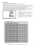
Page 22: ... at any chimney joint A Chimney Requirements Vertical distances are measured from the base of the fireplace as shown in Figure 5 1 5 Chimney and Termination Requirements Table 5 2 Chimney Component Dimensions Table 5 1 Chimney Requirements Minimum overall straight height 13 ft 3 96 m Minimum height with offset return 14 5 ft 4 42 m Maximum height 50 ft 15 24 m Maximum chimney length between an off...

Page 23: ...in 32 mm Effective length is built into this chart B Offsets Returns Use an offset return to bypass overhead obstructions An offset and return can be used as a single entity or separated by chimney section s Warning Risk of Fire Do not use offset returns greater than 30 Chimney draft will be restricted and could cause overheating and fire Secure offsets with screws not to exceed 1 2 13 mm in lengt...

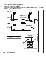
Page 24: ... cap cover s this distance may need to be increased Refer to the installation instructions supplied with the decorative cap cover In a staggered installation with both gas and wood terminations the wood termination cap must be higher than the gas termination cap Figure 5 3 Multiple Chimney Locations C Termination Requirements Install a cap approved and listed for this fireplace system Locate cap w...

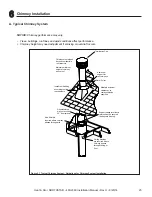
Page 25: ...ical Support straps for offsets returns must be secured to adequate framing Ceiling firestops are required where chimney passes through ceiling or floor Attic Shield is required where chimney passes through attic Figure 6 1 Typical Chimney System Guidelines for Chimney System Installation Notice Chimney performance may vary Trees buildings roof lines and wind conditions affect performance Chimney ...

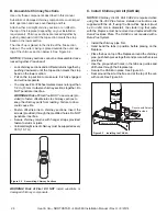
Page 26: ...lly engaged and will not separate You may use 6 or 8 sheet metal screws no longer than 1 2 in 13 mm to fasten chimney sections together Do NOT penetrate inner flue Warning Risk of Fire You MUST use screws pro vided to fasten offset returns to chimney sections to keep the chimney parts from twisting Failure to do so could cause fire Fasten offset returns to chimney sections Insert the screws provid...

Page 27: ...eal around the cap and flex with caulk to stop air from getting into the chase see Figures 6 4 Wire Ties Seal Seal 4 Duct Use UL181 Class 0 or Class 1 ducting Figure 6 4 Installing Flex Pipe WARNING Risk of Fire The flex pipe must never be compressed or deformed Restricting the airflow inside the flex pipe may increase flue pipe temperatures causing a chase fire 27 Heat Glo NORTHSTAR 480 2360 Inst...

Page 28: ...ce 2 in 51mm clearance Catalog A B in mm in mm FS338 14 1 2 368 14 1 2 368 FS339 14 1 2 368 18 3 8 467 FS340 14 1 2 368 23 584 Warning Risk of Fire Do NOT seal area between firestop opening and chimney pipe except where they en ter the attic or leave the warm air envelope of the home use 600 F sealant Figure 6 6 Installing the Ceiling Firestop When offsets and returns are joined to straight pipe s...

Page 29: ... against pipe Attic Insulation Shield Ceiling Firestop 10 1 2 in 267 mm 14 1 2 in 368 mm diameter Insulation Insulation Pipe Pipe 2 in 51 mm air space Tabs bent in 90 and taped Tabs bent in to rest against pipe Attic Insulation Shield Ceiling Firestop 10 1 2 in 267 mm 14 1 2 in 368 mm diameter Insulation Insulation Pipe Pipe 2 in 51 mm air space Figure 6 8 Install Attic Insulation Shield firestop ...

Page 30: ...nt where the chimney will exit the roof by plumbing down to the center of the chimney Lay out cut and frame a 14 1 2 in 368 mm square opening measured on the horizontal through the ceiling and roof structure Consult local codes for framing details The thimble must extend completely through the roof structure shielding combustible materials Five location holes have been provided to allow for a vari...

Page 31: ...r around pipe opening to keep water out Provide a 1 8 in 3 mm gap around the flue pipe Slope the chase top downward away from the opening Warning Risk of Fire Do not caulk the pipe to the chase top collar Caulk all seams to prevent leaks Slope Downward 1 4 in per foot minimum Turn down Drip Edge Chase 2 in 51 mm Collar on Chase Top 018 26 ga min Galvanized Chase Top Figure 6 14 Chase Top Construct...

Page 32: ... Termination Cap Chase 14 1 2 in 368 mm Maximum Collar 2 in 51 mm Minimum Height Caulk gaps between storm collar pipe and storm collar chase top Do NOT block air holes 3 clip brackets Slip over chase collar and attach with screws provided Termination cap pipe and chimney section must overlap 1 1 2 in 38 mm Assemble storm collar around extended termination cap pipe once cap is installed Figure 6 16...

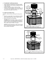
Page 33: ...under each flange of the termination cap and on top of each screw to help prevent leaks 2 in 51 mm maximum 4 3 4 in 121 mm maximum The last section of pipe must stop between 2 in 51 mm above the top of the chase and 4 3 4 in 121 mm below the top of the chase Figure 6 18 Installing a TS345 TS345P Square Termination Cap Chimney Pipe Chase Top Termination Cap Chase Collar 2 in 51 mm Minimum Height Re...

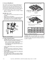
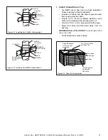
Page 34: ...ve fascia must be removable for future serviceability of the automatic combustion control Figure 7 1 Install the Finishing Template Note DO NOT remove hang tags until installing finish materials B Finish the Wall Use a wet or dry towel or a soft brush to remove any dust or dirt from the non combustible facing material Apply a non combustible adhesive to attach tile stone or other non combustible f...

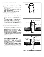
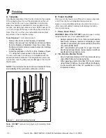
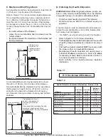
Page 35: ...or minimum dimensions This fireplace has been tested and approved for use with a hearth extension insulated to a minimum R value of 2 06 The hearth extension material MUST be covered with tile stone or other non combustible material Manufactured hearth materials will usually have a published R value resistance to heat or k value conductivity of heat Refer to the formula in Table 7 1 to convert a k...

Page 36: ...stible finish material Figure 7 5 Fireplace and Hearth Extension Flush on the Floor Raised Hearth Extension Framing The hearth framing must be constructed of non combustible materials such as metal framing or equivalent material and topped with two HX4s or equivalent material Table 7 2 When creating the platform allow for the thickness of the non combustible finishing materials Figure 7 6 Outer Ca...

Page 37: ...with non combustible grout to prevent risk of fire and cold air infiltration 45 1 2 in 1156 mm 45 1 2 in 1156 mm NON COMBUSTIBLE ZONE Figure 7 7 E Non Combustible Sealant Material After completing the installation of non combustible material in the required non combustible zone and the non combustible finishing material over that remove the template A bead of non combustible sealant or Super Calst...

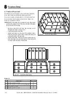
Page 38: ... shown in Figure 8 2 Lay bottom bricks in firebox Install rear bricks on the top of the bottom bricks Slide top of bricks under clip on back of firebox wall and push bottom of brick back Install side bricks Slide top of brick under clips on side of firebox and push the bottom of the brick until it is flush with the side of the firebox Figure 8 1 Fire Brick Configurations Figure 8 2 Fire Brick Conf...

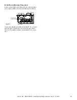
Page 39: ...ssing The ceramic blanket and baffle board MUST be in contact with the back of the firebox and even with each other in the front The baffle protection channel MUST be in posi tion Figure 8 3 Ceramic Blanket Back of Firebox Baffle Board Baffle Protection Channel in position 39 Heat Glo NORTHSTAR 480 2360 Installation Manual Rev H 8 20 14 ...

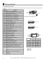
Page 40: ...ing Flat to 6 12 Pitch RF371 Roof Flashing 6 12 to 12 12 Pitch DTO134 146 Octogonal Decorative Caps DTS134 146 Square Decorative Caps ST375 Square Termination Cap TCT375 Terra Cotta Termination Cap TR344 Round Termination Cap TR342 Round Telescoping Termination Cap TR TVK TR Top Vent Kit TS345 Square Termination Cap TS345P Square Termination Cap Painted TV342 Top Vent Round Termination Cap 12966A ...

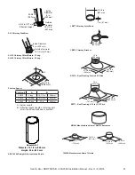
Page 41: ...r 8 in 203 mm Outside Diameter 10 1 2 in 267 mm 4 3 4 in 121 mm Effective Height SL3 Chimney Stabilizer Inside Diameter 8 in 203 mm Outside Diameter 10 1 2 in 267 mm SL315 Chimney Offset Return 15 deg SL330 Chimney Offset Return 30 deg AS8 SL300 Straight Attic Insulation Shield 2 in 51 mm 10 1 2 in 267 mm JB877 Chimney Joint Band 10 1 2 in 267 mm CB876 Chimney Bracket MH841 Manufactured Home Thimb...

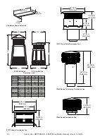
Page 42: ...4 21 18 24 mm 864 538 610 DTS146 in 46 21 18 26 mm 1168 538 660 23 in 584 mm 19 in 483 mm 15 5 8 in 397 mm ST375 Square Termination Cap 22 1 2 in 572 mm 9 1 2 in 241 mm 16 1 2 in 419 mm 9 1 2 in 241 mm TCT375 Terra Cotta Termination Cap 34 3 4 in 883 mm 32 1 2 in 826 mm TR342 Round Telescoping Termination Cap 15 3 4 in 400 mm TR344 Round Termination Cap 42 Heat Glo NORTHSTAR 480 2360 Installation ...

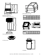
Page 43: ...870 mm TV342 Top Vent Round Termiantion Cap A B C D Catalog A B C D in mm in mm in mm in mm LDS33 36 914 36 914 8 5 216 11 279 LDS46 48 1219 72 1829 8 5 216 11 279 LDS33 LDS46 Decorative Shroud Catalog A B C D E LDS BV in 26 12 5 15 5 22 23 mm 660 318 394 533 584 E D A C B LDS BV Decorative Shroud 26 in 7 3 4 in CT 3A Adapter 43 Heat Glo NORTHSTAR 480 2360 Installation Manual Rev H 8 20 14 ...

Page 44: ...ille MN 55044 www heatnglo com Please contact your Heat Glo dealer with any questions or concerns For the location of your nearest Heat Glo dealer please visit www heatnglo com B Accessories MESH HHT Firescreen 44 Heat Glo NORTHSTAR 480 2360 Installation Manual Rev H 8 20 14 ...

Reviews: