Heat & Glo • Supreme-XTS, Grand-XTS • 349-901 Rev. G • 9/08
40
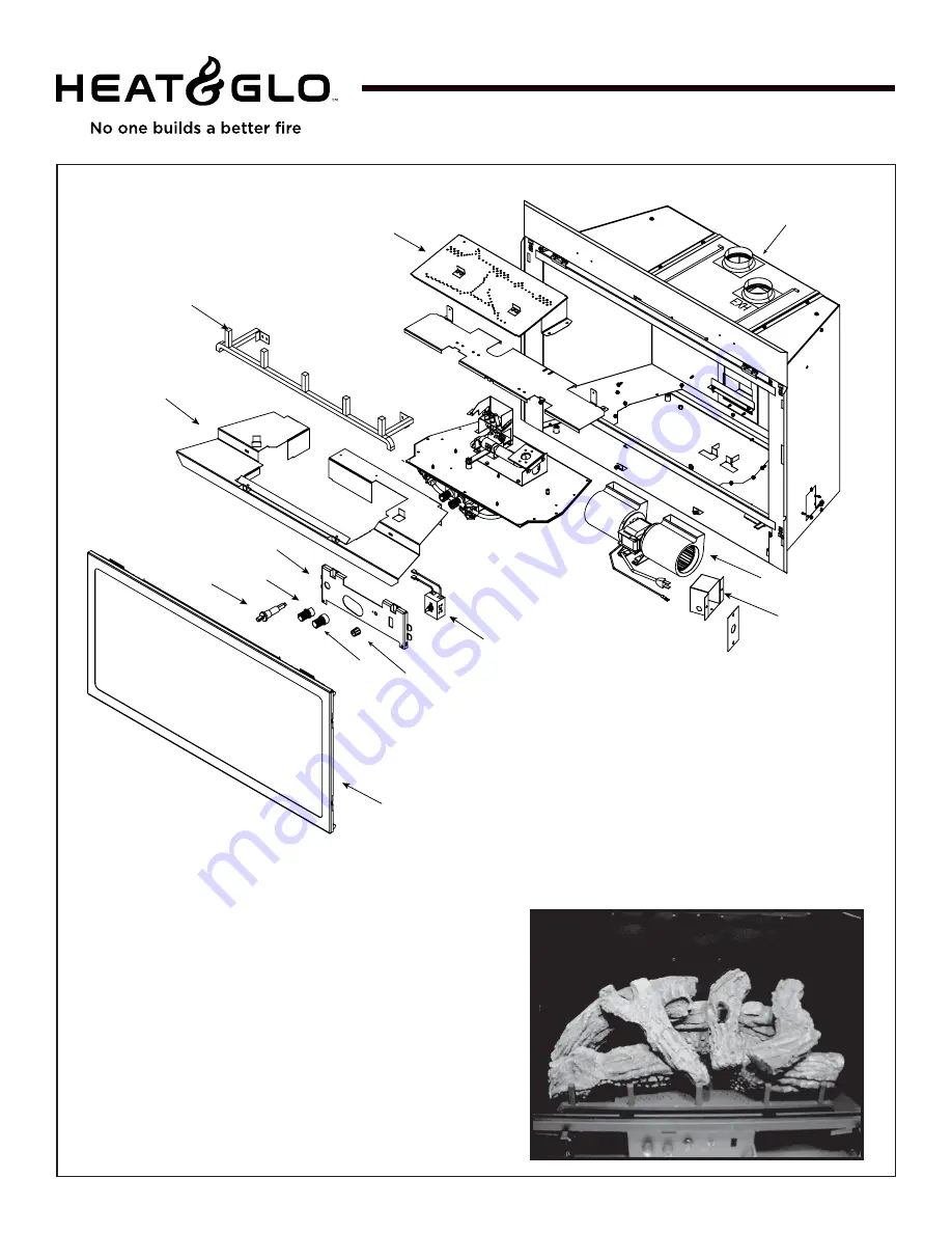
Service Parts Diagram
GRAND-XTS
Beginning Manufacturing Date: Aug. 2007
Ending Manufacturing Date: ______
Service Parts
Part number list on following page.
Log Set Assembly
1
2
3
7
6
4
5
8
20
19
18
17
16
15
14
13
12
11
10
9


