background image

HOW TO PUT ON THE CHEST PULSE SENSOR

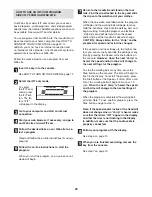
The chest pulse sensor consists of two components:
the chest strap and the sensor unit (see the drawing
below). Insert the tab on one end of the chest strap into
the hole in one end of the sensor unit, as shown in the
inset drawing. Press the end of the sensor unit under
the buckle on the chest strap. The tab should be flush
with the front of the sensor unit.

Next, wrap the chest
pulse sensor around
your chest and attach
the other end of the
chest strap to the
sensor unit. Adjust
the length of the
chest strap, if neces-
sary. The chest pulse
sensor should be under your clothes, tight against your
skin, and as high under the pectoral muscles or
breasts as is comfortable. Make sure that the logo on
the sensor unit is facing forward and is right-side-up.  

Next, pull the sensor unit away from your body a few
inches and locate the two electrode areas on the inner
side (the electrode areas are covered by shallow
ridges). Using saline solution such as saliva or contact
lens solution, wet both electrode areas. Return the
sensor unit to a position against your chest. 

CHEST PULSE SENSOR CARE AND MAINTENANCE

• Thoroughly dry the chest pulse sensor after each

use. The chest pulse sensor is activated when the
electrode areas are wetted and the heart rate 
monitor is put on; the chest pulse sensor shuts off
when it is removed and the electrode areas are
dried. If the chest pulse sensor is not dried after 
each use, it may remain activated longer than nec-
essary, draining the battery prematurely.

• Store the chest pulse sensor in a warm, dry place. 

Do not store the chest pulse sensor in a plastic bag
or other container that may trap moisture. 

• Do not expose the chest pulse sensor to direct sun-

light for extended periods of time; do not expose it to
temperatures above 50° C (120° F) or below -10° C
(15° F). 

• Do not excessively bend or stretch the sensor unit

when using or storing the chest pulse sensor.

• Clean the sensor unit using a damp cloth—never

use alcohol, abrasives, or chemicals. The chest
strap may be hand washed and air dried.

CHEST PULSE SENSOR TROUBLESHOOTING

The instructions on the following pages explain
how the chest pulse sensor is used with the con-
sole. If the chest pulse sensor does not function
properly, try the steps below.

• Make sure that you are wearing the chest pulse sen-

sor as described at the left. Note: If the chest pulse
sensor does not function when positioned as de-
scribed, move it slightly lower or higher on your chest.

• Use saline solution such as saliva or contact lens

solution to wet the two electrode areas on the sensor
unit. If heart rate readings do not appear until you
begin perspiring, rewet the electrode areas.

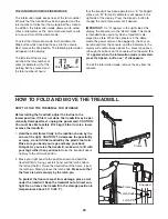
• As you walk or run on the treadmill, position your-

self near the centre of the walking belt. 

For the con-

sole to display heart rate readings, the user must
be within arm’s length of the console.

• The chest pulse sensor is designed to work with

people who have normal heart rhythms. Heart rate
reading problems may be caused by medical condi-
tions such as premature ventricular contractions
(pvcs), tachycardia bursts, and arrhythmia.

• The operation of the chest pulse sensor can be af-

fected by magnetic interference caused by high
power lines or other sources. If it is suspected that
this is a problem, try relocating the treadmill.

• The CR2032 battery may need to be replaced (see

page 28).

Chest Strap

Tabs

Sensor Unit

Tab

Sensor

Unit

Buckle

HOW TO USE THE CHEST PULSE SENSOR

9

Summary of Contents for H500 Treadmill

Page 1: ...plete satis faction through direct assistance from our factory TO AVOID DELAYS PLEASE CALL DIRECT TO OUR TOLL FREE CUSTOMER HOT LINE The trained technicians on our Customer Hot Line will provide immediate assistance free of charge to you CUSTOMER HOT LINE 800 820 0915 E mail newlife vip 163 com ICON s Web site www iconfitness com Newlife is an authorized dealer of this treadmill in the territory o...

Page 2: ...LSE SENSOR 9 OPERATION AND ADJUSTMENT 10 HOW TO FOLD AND MOVE THE TREADMILL 24 TROUBLESHOOTING 26 CONDITIONING GUIDELINES 29 PART LIST 30 ORDERING REPLACEMENT PARTS Back Cover Note An EXPLODED DRAWING is attached in the centre of this manual HealthRider is a registered trademark of ICON IP Inc 2 ...

Page 3: ...s 13 Never move the walking belt whilst the power is turned off Do not operate the treadmill if the power cord or plug is damaged or if the treadmill is not working properly See TROU BLESHOOTING on page 26 if the treadmill is not working properly 14 Never start the treadmill whilst you are stand ing on the walking belt Always hold the handrails whilst using the treadmill 15 The treadmill is capabl...

Page 4: ...insert any object into any opening 25 DANGER Always unplug the power cord immediately after use before cleaning the treadmill and before performing the maintenance and adjustment procedures de scribed in this manual Never remove the motor hood unless instructed to do so by an authorised service representative Servicing other than the procedures in this manual should be performed by an authorised s...

Page 5: ... manual see the front cover of this manual To help us assist you please note the product model number and serial number before calling The model number of the treadmill is HATL51205 0 The serial number can be found on a decal attached to the tread mill see the front cover of this manual for the location Before reading further please familiarise yourself with the parts that are labelled in the draw...

Page 6: ...pose of the packing materials until assembly is completed Note The underside of the treadmill walking belt is coated with high performance lubricant During shipping a small amount of lubricant may be transferred to the top of the walking belt or the shipping carton This is a normal condition and does not affect treadmill perfor mance If there is lubricant on top of the walking belt simply wipe off...

Page 7: ...refully tip the Uprights 97 down as shown Note It may be helpful to place one foot against one of the Extension Legs 115 as you tip the Uprights Make sure that the Extension Legs remain in the Uprights Attach each Extension Leg 115 with two Extension Leg Bolts 80 and two 1 4 Washers 39 as shown 80 115 80 80 115 97 39 39 2 39 39 3 Attach the four Base Pads 99 to the base of the Uprights 97 with fou...

Page 8: ...13 5 See drawing 5c With the help of a second person hold the Console Base 101 near the Uprights 97 Look under the Console Base and locate the wires on the sides of the Console Base Make sure that the wires are not routed through the openings for the Trays 111 112 Drawing 5a shows the correct route for the wires Drawing 5b shows an incorrect route See drawing 5c Cut the plastic ties holding the Wi...

Page 9: ...c bag or other container that may trap moisture Do not expose the chest pulse sensor to direct sun light for extended periods of time do not expose it to temperatures above 50 C 120 F or below 10 C 15 F Do not excessively bend or stretch the sensor unit when using or storing the chest pulse sensor Clean the sensor unit using a damp cloth never use alcohol abrasives or chemicals The chest strap may...

Page 10: ...ug Important If the power cord is damaged it must be replaced with a manufacturer recommended power cord See drawing 1 Plug the indicated end of the power cord into the socket on the treadmill See drawing 2 Plug the power cord into an appropriate outlet that is properly installed and earthed in accordance with all local codes and ordinances Important The treadmill is not compatible with GFCI equip...

Page 11: ...r sonal trainer in your home Using a stereo audio cable you can connect the treadmill to your portable stereo home stereo computer or VCR and play special iFIT com MP3 CD and video programs iFIT com MP3 programs CDs and videocassettes are available sepa rately IFIT com programs automatically control the speed and incline of the treadmill as a personal trainer guides you through every step of your ...

Page 12: ...g belt as desired by pressing the Speed and buttons Each time a button is pressed the speed setting will change by 0 1 mph if a but ton is held down the speed setting will change in increments of 0 5 mph Note After the buttons are pressed it may take a moment for the walking belt to reach the selected speed setting If one of the ten numbered buttons is pressed the walking belt will gradually incre...

Page 13: ...ay your heart rate accurately To use the handgrip pulse sensor first remove the sheets of clear plastic from the metal contacts on the handrail Next stand on the foot rails and hold the metal contacts avoid moving your hands When your pulse is detected the heart symbol in the right side of the display will appear one or two dashes will appear and then your heart rate will be shown For the most acc...

Page 14: ...o change the speed setting and or incline setting will flash in the dis play to alert you When the first segment ends all speed settings will move one column to the left The speed set ting for the second segment will then be shown in the flashing Current Segment column and the treadmill will automatically adjust to the speed and incline settings for the second segment Note If all five of the indic...

Page 15: ... into the console See HOW TO TURN ON THE POWER on page 12 Select one of the speed programs To select one of the speed programs press the Speed Program but ton repeat edly As each speed pro gram is selected the maximum speed setting of the program will flash in the display for a few sec onds The display will also show how long the pro gram will last The matrix in the lower part of the display will ...

Page 16: ... in the display see the drawing above If de sired press the Incline increase or decrease but ton to change the maximum target heart rate set ting see EXERCISE INTENSITY on page 29 Note If the maximum target heart rate setting is increased or decreased the intensity level of the entire program will increase or decrease Press the Start button or the Speed button to start the program A moment after t...

Page 17: ... during the program you can adjust the setting with the Speed or Incline buttons However each time the console compares your heart rate to the target heart rate setting the speed and or in cline of the treadmill may automatically change to bring your heart rate closer to the target heart rate If your pulse is not detected during the program the letters PLS will flash in the display and the speed a...

Page 18: ...t program Enter your age Next the word AGE and the current age setting will appear in the display If you have not entered your age press the Incline in crease or decrease button repeatedly to enter your age Press the Start button or the Speed button to start the program A moment after the button is pressed the tread mill will automatically adjust to the first speed and incline settings of the prog...

Page 19: ... If your stereo has a 3 5 mm LINE OUT jack see instruction B If your stereo has only a PHONES jack see instruction C A Plug one end of a long 3 5 mm to RCA stereo audio cable available at electronics stores into the input jack on the console Plug the other end of the cable into the AUDIO OUT jack on your stereo B See the drawing above Plug one end of a long 3 5 mm to 3 5 mm stereo audio cable avai...

Page 20: ...res Next remove the wire that is currently plugged into the LINE OUT jack on your stereo and plug the wire into the unused side of the Y adapter Plug the Y adapter into the LINE OUT jack on your stereo Note Whilst the Y adapter is plugged into the LINE OUT jack do not plug your headphones into the headphone jack on the console HOW TO CONNECT YOUR COMPUTER A Plug one end of a long 3 5 mm to 3 5 mm ...

Page 21: ... cover of this manual Follow the steps below to use an iFIT com MP3 CD or video program Insert the key into the console See HOW TO TURN ON THE POWER on page 12 Select the iFIT com mode To select the iFIT com mode press the iFIT but ton The let ters iFIT will appear in the display Press the Play button on your MP3 player CD player or VCR Note If you are using an iFIT com CD insert the CD into your ...

Page 22: ...ncline of the treadmill does not change when a chirp is heard Make sure that the letters iFIT appear in the display and that the time is not flashing in the display If the time is flashing press the Start button or the Speed button on the console Adjust the volume of your MP3 player CD player or VCR If the volume is too high or too low the console may not detect the program signals Make sure that ...

Page 23: ...untdown ends the program will begin and the walking belt will begin to move Hold the handrails step onto the walking belt and begin walking During the program an electronic chirping sound will alert you when the speed and or incline of the treadmill is about to change CAUTION Always listen for the chirp and be prepared for speed and or incline changes If the speed or incline settings are too high ...

Page 24: ...MO MODE The information mode keeps track of the total number of hours that the treadmill has been operated and the total number of miles that the walking belt has moved In addition the information mode allows you to select miles or kilometers as the unit of measurement and to turn on and turn off the demo mode To select the information mode first hold down the Stop button whilst inserting the key ...

Page 25: ...ne foot against one of the wheels and carefully lower the treadmill until it is resting in the storage position HOW TO LOWER THE TREADMILL FOR USE 1 Hold the upper end of the treadmill with your right hand as shown Using your left hand pull the latch knob to the left and hold it Pivot the treadmill down until the frame is past the latch pin Slowly release the latch knob 2 Hold the metal frame firm...

Page 26: ...ch back in d Check the on off switch located on the treadmill frame near the power cord Make sure that the switch is in the on position PROBLEM The power turns off during use SOLUTION a Check the circuit breaker located on the treadmill frame near the power cord see c above If the circuit breaker has tripped wait for five minutes and then press the switch back in b Make sure that the power cord is...

Page 27: ...red Plug in the power cord insert the key and walk on the treadmill for a few minutes Repeat until the walking belt is properly tightened c If the walking belt still slows when walked on see the front cover of this manual PROBLEM The walking belt is off centre or slips when walked on SOLUTION a If the walking belt is off centre remove the key and UNPLUG THE POWER CORD If the walking belt has shift...

Page 28: ...xt remove the old battery from the sensor unit and insert a new CR 2032 battery with the battery oriented so the writing on top Make sure that the rubber gasket is in place in the sensor unit Then reinsert the battery cover and turn it to the closed position PROBLEM The incline of the treadmill does not change correctly SOLUTION a With the key in the console press one of the Incline buttons Whilst...

Page 29: ...hat requires large amounts of oxygen for prolonged periods of time This increases the demand on the heart to pump blood to the muscles and on the lungs to oxygenate the blood For aerobic exercise adjust the speed and incline of the treadmill until your heart rate is near the highest number in your training zone WORKOUT GUIDELINES Each workout should include the following three parts A Warm up Star...

Page 30: ... Shock 46 1 Controller Bracket 47 1 On Off Switch 48 1 Controller 49 1 Power Cord 50 2 Upright Endcap Small 51 1 Circuit Breaker 52 1 Receptical 53 3 Belly Pan Clip 54 1 Belly Pan 55 2 Releasable Tie 56 1 Photo Switch Wire 57 2 Tie Holder Clamp 58 9 Cable Tie 59 1 Frame 60 1 Right Rear Foot 61 1 Idler Nut 62 2 Rear Roller Adj Bolt 63 1 Rear Roller 64 1 Hex Key 65 1 Chest Pulse Sensor 66 1 Left Rea...

Page 31: ...111 1 Right Accessory Tray 112 1 Left Accessory Tray 113 4 Internal Star Washer 114 1 Latch Insert 115 2 Extension Leg 116 2 Base Endcap 117 2 Upright Endcap Large 1 8 Black Wire R R 1 6 Black Wire R R 2 4 Black Wire F F 1 6 G Y F R 1 4 G Y F R 1 4 Green Wire M Ring 2 10 White Wire F F 1 10 Blue Wire F F 1 4 Red Wire F M 1 User s Manual These parts are not illustrated Specifications are subject to...

Page 32: ...7 7 41 39 12 83 56 35 10 6 10 6 44 93 44 53 53 44 9 48 95 108 20 37 102 100 73 98 78 34 11 25 46 14 5 44 85 35 88 88 44 108 30 29 108 84 86 75 79 23 61 72 71 20 109 32 28 36 52 39 39 108 51 73 100 78 108 57 26 80 49 EXPLODED DRAWING Model No HATL51205 0 R0805A To identify the parts shown on this EXPLODED DRAWING see the PART LIST on pages 30 and 31 of the User s Manual ...

Page 33: ...50 89 113 89 113 50 116 92 104 108 106 108 107 81 31 43 44 44 44 44 44 44 44 44 44 44 44 44 44 103 96 111 44 44 44 44 44 44 44 101 112 44 44 44 76 44 27 44 44 44 44 105 87 115 80 39 99 40 80 39 108 108 108 117 116 115 65 70 44 57 99 40 99 40 44 3 8 108 EXPLODED DRAWING Model No HATL51205 0 R0805A ...

Page 34: ...ct to any economic loss loss of property loss of revenues or profits loss of enjoyment or use costs of removal or installation or other consequential damages of whatsoever nature Some states do not allow the exclusion or limitation of in cidental or consequential damages Accordingly the above limitation may not apply to you The warranty extended hereunder is in lieu of any and all other warranties...

Reviews: