iLogger easy User Manual [rev. 002] | www.healtech-electronics.com/iLE
6/6
There’s the possibility to select a single lap from
the lap times charts. By tapping on the given lap,
a bright yellow background would appear in the
graph viewer area marking the selected lap.
9.4 MAP
While the recorded session contains valid GPS
data, the routes ridden are visible in a map view.
Tap the
MAP
button in the left vertical menu to
activate the map display feature.
The location of the red dot on the map
corresponds to the position of the yellow cursor in
the graph viewer. By swiping the graphs, the red
dot will move accordingly. This is a great help to
understand what is happening at a specific point
of the track.
To help riders better understand their riding,
we’ve added a coloring option to the map viewer.
This colors the track according to one channels’
values. To activate this, tap the header of the map
viewer. By default ‹
no coloring
› is being displayed
in the header. By tapping it you can select the
channel you would like to be presented on the
track map. The deep blue color represents the
lowest value of the selected channel. The higher
the value, the color shifts first to green and finally
to red.
In case a lap has been selected from the lap chart
the coloring on the map represents only that lap.
9.5 ZOOM
By tapping the ZOOM button in the left vertical
menu, the user can switch between the following
zoom states in the graph viewer:
- Whole session / complete view:
The whole length
of the session is shown.
- Cursor area:
1 minute / 2 kilometers (1.25 miles)
is shown in the graph area.
- Selected lap:
The lap selected from the chart in
the lap viewer is displayed.
By tapping the ZOOM button continuously, the view
cycles through the three zoom states.
11.
LED statuses / error warnings
10.
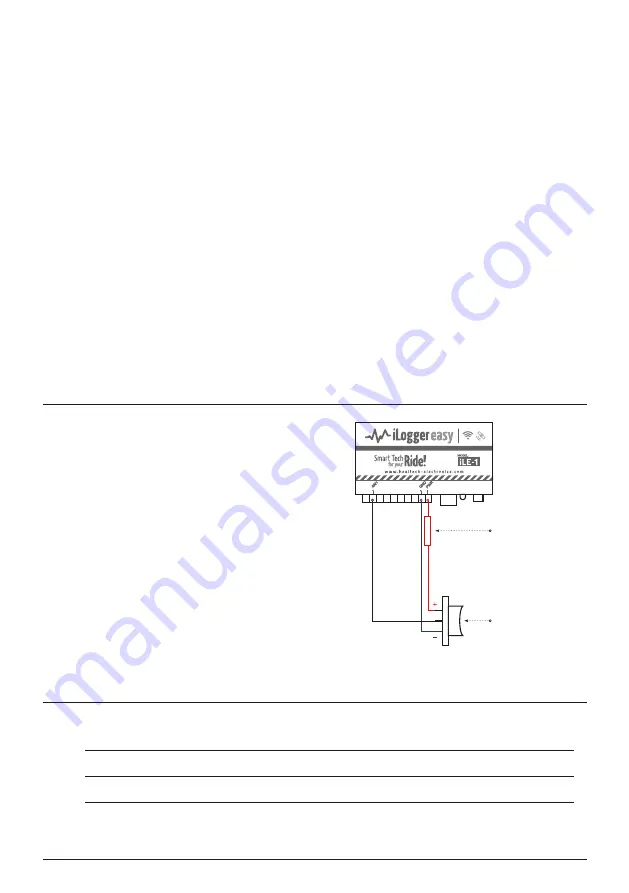
External switch for AR Assistant
Explanations of the iLE module’s built-in bi-color status LED (red/green) signals:
Continuous red:
Module in boot/startup phase.
Continuous green:
Module operating normally.
Flashing green:
Recording in progress.
Flashing red and green:
Malfunction / operation error.
It is possible to connect an external switch to the
AN1
input as shown on the right.
We recommend using a 3-way momentary switch,
which makes contact to
+12V
when pushed
upwards and makes contact to
GND
when pushed
downwards. When you release the switch, it should
revert to the default middle (off) position.
It is essential to use a limiting resistor of 2.7Kohms
in the PWR connection, otherwise an accidental
short circuit at the switch may cause severe
problems.
After connecting the switch, configure the AN1
input in the app to be used as AW-TC sensitivity
adjustment switch for the AR Assistant module.
The actual AW-TC sensitivity value will be displayed
on the iLE live dashboard.
Advanced telemetry and data acquisition system
2.7K resistor
3-way
momentary
switch


