HDVision DVR16H Quick Setup Manual Download Page 3

3

www.Observint.com

© 2018 Observint Technologies, Inc. All rights reserved. 

CAUTION

Do not apply power to the DVR at this time. 

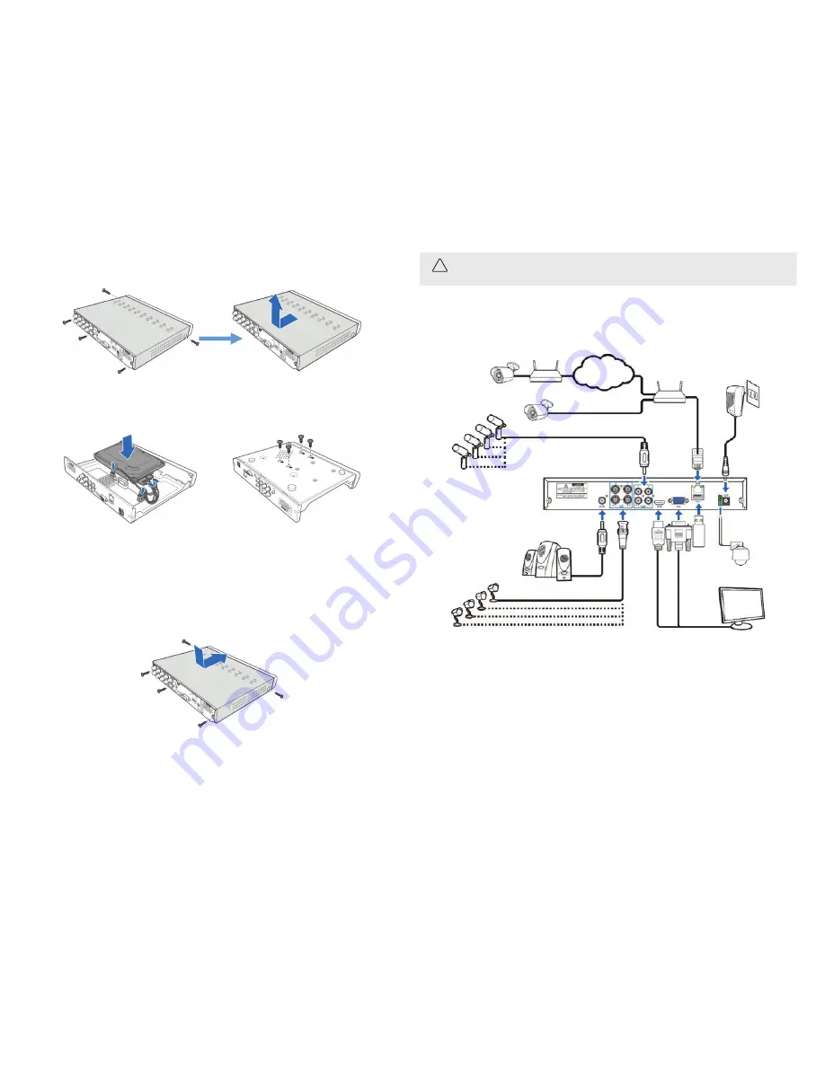
Step 3.  Connect devices to the DVR

Your DVR security system is highly configurable to meet your application requirements. The diagram below illustrates how the DVR can be 
interconnected to various devices. Refer to the 

Specifications

 section for more information about the capacity of your DVR. 

Analog 

Cameras

Network Cameras

Power  

adapter

PTZ 

Camera

Internet cloud

Monitor

Router

RS485  

network

Ethernet

Ethernet

Mouse  

or Flash  

Media

Router

Speakers

VGA or  

HDMI

Microphones

Cameras

Install your security cameras. Always follow the installation instructions provided with the camera. 
1. 

Install the analog cameras that will connect to the 

VIDEO INPUT

 connectors on the back of the DVR. 

2. 

Route video / power extension cable(s) between the cameras and the DVR. Note that power connectors on some extension cables 
are different: the power connector at the camera is a male style connector, and the power connector at the source (usually DVR) is a 
female style connector. 

3. 

Connect the extension cable(s) to the camera and the DVR. 

Install a monitor, mouse, microphones, network, power etc 

For the following steps, refer to the back panel photo above for the location of connectors. 
1. 

Install and setup your monitor in accordance with the instructions provided with the monitor. Do not power it on at this time. 

The example shown here is for an R16 DVR. To install an HDD: 
1. 

Lay the DVR on a clean, flat table, and then remove the five cover screws shown in the picture below on the left. 

2. 

Slide the cover back, then lift it off the DVR chassis. 

3. 

Unpackage your HDD(s). 

4. 

Connect a SATA cable and one of the HDD power cables to the HDD as shown in the picture below on the left. 

5. 

Position the HDD in the chassis, aligning the holes in the bottom of the chassis with the with the mounting screw holes on the 
underside of the HDD. 

6. 

Holding the HDD in place, turn over the DVR with the HDD, and then use four (4) screws to attach the HDD to the chassis. 

7. 

Lay the DVR on the table, top up. Check the to make sure the SATA and power cables are fully seated both on the HDD and the chassis 
PC board. 

8. 

Install a second HDD if needed and the chassis has space for it. 

9. 

Reinstall the cover on the DVR. 

Install the DVR 

1. 

Place the DVR in a location that is secure, well ventilated and clean. The DVR should be positioned such that the back panel connectors 
are accessible and the ventilation holes on the top and sides are not blocked. 

2. 

Connect the ground terminal (if available) on the back of the DVR to an earth ground. Refer to local electrical codes for proper 
grounding. 

Summary of Contents for DVR16H

Page 1: ...mouse 1 Plug the USB mouse into the either the front panel or back panel USB connector of the DVR 2 When the recorder is powered on the mouse will be automatically detected If the mouse is not detected the mouse may not be compatible with the DVR Please refer to the recommended device list from your provider This guide provides instructions to initially setup the R16 16 channel digital video recor...

Page 2: ...security grade HDDs in your DVR The chassis is designed to accommodate both 3 5 inch and 2 5 inch HDDs with an HDD capacity up to 8 TB CAUTION Beforeperformingthisprocedure ensurethatthepowercordis notdisconnectedfrom the DVR Using the mouse 1 Left Button Click to select menu options During live viewing in split screen view double click on a channel to view it in full screen Double click the chann...

Page 3: ...e back panel photo above for the location of connectors 1 Install and setup your monitor in accordance with the instructions provided with the monitor Do not power it on at this time The example shown here is for an R16 DVR To install an HDD 1 Lay the DVR on a clean flat table and then remove the five cover screws shown in the picture below on the left 2 Slide the cover back then lift it off the D...

Page 4: ... cable from your local area network LAN router into the RJ45 LAN connector on the back of the DVR 6 If using speakers plug your speaker set into the AUDIO OUT RCA connector on the back of the DVR The AUDIO OUT connector provides a line level signal output An audio adapter may be needed to connect your speaker set to the DVR RCA connector 7 If using an RS485 network to control a PTZ camera or other...

Page 5: ...ange the port numbers of your DVR consider the following Web Port This is the port that you will use to log in remotely to the DVR e g using the Web Client If the default port 80 is already taken by other applications please change it Client Port This is the port that the DVR will use to send information through e g using the mobile app If the default port 9000 is already taken by other applicatio...

Page 6: ... from the list above ii Open the Overwrite drop down list and then select Auto PPPoE PPPoE is an advanced protocol that allows the DVR to connect to the network more directly via DSL modem Check the Enable PPPOE box and then enter the User name and Password of the PPPoE c Click Next to continue 3 Use the Date Time menu to set the Date Time Date Format Time Format Time Zone NTP and DST daylight sav...

Page 7: ...st above ii Click the Format button Allow the format operation to complete before continuing 6 Click Next to continue Use the Resolution menu to select an output resolution that matches your monitor The DVR automatically adjusts the output resolution during start up to match the highest resolution of your monitor 7 To change the resolution open the drop down list select the resolution you prefer a...

Page 8: ...5MP Model Analog 5MP 20 fps 4MP 3MP 30 fps 1080P 720P 960H IP 4MP 3 MP 1080P 720P 4K Model Analog 8MP 15 fps 5MP 20 fps 4MP 3MP 1080P 720P 960H 30 fps 5MP Model Analog 5MP 20 fps 4MP 3MP 30 fps 1080P 720P 960H The Live View screen includes several useful features Camera Title A This indicates that the camera connected is an AHD camera T This indicates that the camera connected is a TVI camera C Th...

Page 9: ...max 4 ch playback 4MP 40 fps 3MP 48 fps 1080P 120 fps 5MP Model max 4 ch playback 5MP 48 fps 4MP 60 fps 1080P 120 fps 4K Model 8MP 28 fps max 4 ch playback 5MP 80 fps max 8 ch playback 4MP 120 fps 3MP 136 fps 1080P 240 fps 5MP Model max 8 ch playback 5MP 104 fps 4MP 136 fps 3MP 184 fps 1080P 240 fps 4K Model 8MP 56 fps max 8 ch playback 5MP 160 fps max 16 ch playback 4MP 240 fps 3MP 272 fps 1080P ...

Reviews: