


3
OPErATION CONTrOLS & FuNCTIONS
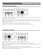
TrANSmITTEr FrONT & rEAr PANELS
q
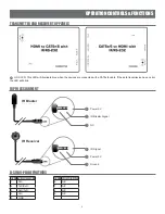
IR OUT/Blaster:
Connect to the supplied IR blaster for IR signal transmission to the source equipment. Place the IR blaster in direct
line-of-sight of the equipment to be controlled.
w
HDMI IN:
Connect to the HDMI input source devices such as a DVD player or a Set-top Box with HDMI cable or DVI to HDMI cable.
e
RS-232 IN:
Connect the 3.5mm mini-jack to D-Sub 9-pin female adaptor cable (included in the package) to a PC or laptop for the
transmission of RS-232 commands.
r
DC 5V:
Plug the 5V DC power supply into the unit and connect the adaptor to an AC outlet.
t
CAT5e/6 OUT:
Connect to the receiver unit with a single CAT5e/6 cable for transmission of all data signals.
rECEIvEr FrONT & rEAr PANELS
q
DC 5V:
Plug the 5V DC power supply into the unit and connect the adaptor to an AC outlet.
w
CAT5e/6 IN:
Connect to the transmitter unit with a single CAT5e/6 cable for transmission of all data signals.
e
IR IN/Extender:
Connect to the supplied IR extender cable for IR signal reception. Ensure that remote being used is within the direct
line-of-sight of the IR extender.
r
HDMI OUT:
Connect to a HDMI equipped TV/monitor for display of the HDMI input source signal.
t
RS-232 OUT:
Connect the 3.5mm mini-jack to D-Sub 9-pin male adaptor cable (included in the package) to a PC or control system
with D-Sub 9-pin cable for the transmission of RS-232 commands.
q
e
w
r
t
q
e
w
r
t