

Page 2 (2)
User manual/Assembly instructions - Fixed back connector
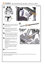
Grasp the push bar with one hand and
pull the locking pin (g). Fold the back
frame backward.
Release the gas spring from the front
of the seat frame by removing the
retaining ring (h) and knocking out the
connecting pin (i).
Roughly adjust the back connector for
the desired angle but do not tighten
the nut (j). When fully screwed in the
connector gives a back angle of ~105°.
Assemble the back connector in the
seat frame with the original pin and
retaining ring.
Note:
The retaining ring must be
handled correctly. If damaged it must
be replaced.
Attach the back frame with the back
connector. Finely adjust the angle
as necessary. Tighten the nut after
adjusting.
Check that connections are secure.
Use and Care instructions
Always replace damaged parts immediately. For more information see
Maintenance Instructions
,
document number 96730-1.
4
5
7
6
8
5
h
i
6
j
7
g
4


