background image

8

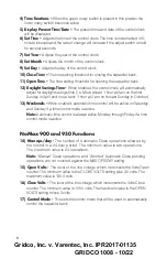
4) Time Functions –

When the upper rotary switch is placed in this position the

lower rotary switch becomes active.

5) Display Present Time/Date –

The present time and date of the control clock

will be displayed.

6) Set Time –

Adjusts the time of the control clock. The time is incremented in 5-

minute intervals and the rate of change will increase if the adjust switch is held

for several seconds.

7) Set Year –

Adjusts the year of the control clock.

8) Set Month –

Adjusts the month of the control clock.

9) Set Day –

Adjusts the day of the control clock.

10) Close Time –

The time setting threshold for closing the capacitor bank.

11) Open Time –

The time setting threshold for opening the capacitor bank.

12) Daylight Savings Time –

When enabled, the control clock will automatically

adjust for daylight savings time (i.e. Move ahead 1 hour at 2am on the first

Sunday in April and move back 1 hour at 2 am on the last Sunday in October).

13) Weekends –

When enabled, automatic time control will be active on Saturday

and Sunday if a time control mode is active.

Note:

Automatic time control is always active Monday through Friday if a time

control mode is active

NoMax 900 and 950 Functions

14) Max ops/day -

The number of Automatic Close operations allowed by

the control in a 24-hour period. The minimum value is two operations.

The maximum value is 24 operations.

Note:

“Manual” Close operations, and “Aborted” Automatic Close pending

operations, are not counted against the MAX OPS/DAY setting.

15) Open Volts -

The level of the line voltage which increments the Volts Open

counter. The minimum value is the CLOSE VOLTS setting plus 3.0 volts. The

maximum value is 130.0 volts.

16) Close Volts -

The level of the line voltage which increments the Volts Close

counter. The minimum value is 105.0 volts. The maximum value is the OPEN

VOLTS setting minus 3 volts.

17) Control Mode -

This sets the control mode that will be used to automatically

control the capacitor bank.

Gridco, Inc. v. Varentec, Inc. IPR2017-01135

GRIDCO 1008 - 10/22

Summary of Contents for NoMAX 900 Series

Page 1: ...Controls the Manual The last page of the Manual bears a 2007 copyright date and includes an identifying reference to Bulletin No NoMax900 200b The Manual was produced by HD Electric Company and was distributed and otherwise provided to users and potential users of the NoMAX 900 Series products as detailed below 5 I am personally familiar with the circumstances surrounding the printing and distribu...

Page 2: ...EXHIBIT A THE MANUAL iNei dis 0 1 1 r 11363886 r4v g31431SAH3 ouetriYAATOv 1t0i8201 1 3 11543595 1 Gridco Inc v Varentec Inc IPR2017 01135 GRIDCO 1008 2 22 ...

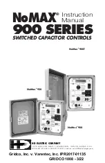
Page 3: ...K E G A N I L L I N O I S 6 0 0 8 5 U S A PHONE 847 473 4980 FAX 847 473 4981 website www HDElectricCompany com NoMAX 900 SERIES SWITCHED CAPACITOR CONTROLS Instruction Manual NoMax 900 NoMax 900T NoMax 950 Gridco Inc v Varentec Inc IPR2017 01135 GRIDCO 1008 3 22 ...

Page 4: ...Gridco Inc v Varentec Inc IPR2017 01135 GRIDCO 1008 4 22 ...

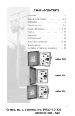
Page 5: ...allation 6 Control Set Up 7 9 Display Messages 10 11 Fusing 11 Operation 12 LED Indicators 13 Automatic Operations 14 18 Specifications 18 Limitation of Warranty Liability 19 NoMax 900T NoMax 900 NoMax 950 Gridco Inc v Varentec Inc IPR2017 01135 GRIDCO 1008 5 22 ...

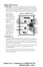
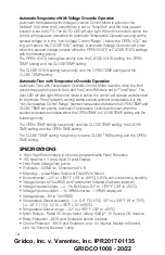
Page 6: ...perature rises above the user selected CLOSE TEMP setting The control will open the capacitor bank when the sensed ambient temperature drops below the user selected OPEN TEMP setting For Winter Schedule defined by OPEN TEMP greater than CLOSE TEMP setting The control will close the capacitor bank when the sensed ambient temperature drops below the user selected CLOSE TEMP setting The control will ...

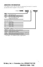
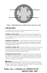
Page 7: ...ride functions 900 Time with temperature and voltage override function VOLTAGE OPTION 1 120V 60Hz 2 240V 60Hz 3 220V 50Hz 4 120V 50Hz MOUNTING OPTION 4RNN 4 stab meter base with mounting ring 4SNN 4 stab meter base ringless PNN Pole bracket mounted with terminal strip specify hole PANN Pole mounted with Amphenol connector See Figure 1 for standard 4 stab wiring diagram Gridco Inc v Varentec Inc IP...

Page 8: ...less Base Align the terminals on the back of the control and press firmly into the meter socket Tighten the 3 locking screws located on the meter base Attach a ground wire to the external ground lug Seal the 3 locking screws only after the entire system has been verified Installing Pole Mounted Controls Pole Mounted Controls are mounted with the included pole bracket and user supplied mounting str...

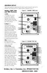
Page 9: ...the setting at a faster rate Continuing to hold the switch increases the adjustment rate Note All of the settings rollover when the maximum or minimum value is exceeded 3 Time Delay This sets the Operation Time Delay period This delay is the amount of time in seconds the control will wait between determining the bank needs to switch states and actually energiz ing the Capacitor Bank Motor Relay Th...

Page 10: ... last Sunday in October 13 Weekends When enabled automatic time control will be active on Saturday and Sunday if a time control mode is active Note Automatic time control is always active Monday through Friday if a time control mode is active NoMax 900 and 950 Functions 14 Max ops day The number of Automatic Close operations allowed by the control in a 24 hour period The minimum value is two opera...

Page 11: ...e capacitor bank will Open when temperature drops below the OPEN TEMP setting 19 Close Temp The temperature setting threshold for closing the capacitor bank The minimum value is 5 degrees The maximum value is 125 degrees The NoMAX 900T prevents the CLOSE TEMP setting from being closer than 5 degrees to the OPEN TEMP setting The control will issue a close command to the capacitor bank based upon th...

Page 12: ...t control clock date Sunday or other day The present control clock day Note All messages which include an equality sign indicates the user is accessing a set point Seconds xxx The OPERATION TIME DELAY setting Max Ops 24 Hr xx The MAX OPS DAY setting Open V xxx x The OPEN VOLTS setting Close V xxx x The CLOSE VOLTS setting Close Temp xxx The CLOSE TEMP setting NoMax 900 only Open Temp xxx The OPEN ...

Page 13: ...ge and Temperature Sensors fail the control will initiate an Open operation If Voltage Only Mode is active and the Voltage Sensor fails the control will initiate an Open operation If Temperature Only Mode is active and the Temperature Sensor fails the control will initiate an Open operation Note 3 While in a failure Mode see Note 2 Manual Close while in AUTO is disabled Manual Close when NOT in AU...

Page 14: ...al operations do not count against the limit set by MAX OPS DAY Five Minute Close Inhibit The controls use a built in time delay to prevent the line from closing into a charged Capacitor Bank This Close Inhibit delay begins after every Open operation and is active for 5 minutes Neither Automatic nor Manual Close operations will take place while Close Inhibit is active Other Operational Features If...

Page 15: ...ode verify the red LED is off and select TIME DELAY Using the ADJUST switch select the desired time delay in seconds from 3 to 600 Use the toggle switch to OPEN or CLOSE the capacitor bank The OPERATION PENDING LED will flash for the duration of the selected time delay The CLOSE or OPEN LED will flash during the time the output is energized and will remain on Note 1 Pending manual operations can b...

Page 16: ...age rises above this set point for one minute continuous the control will open the capacitor bank after the preset time delay Use the Adjust switch to select the desired value The minimum value is the Close Volts setting plus 3 volts The maximum value is 130 volts 2 CLOSE VOLTS is the set point for closing the capacitor bank based upon sensed line voltage When the sensed line voltage drops below t...

Page 17: ...se if a Volts Close operation is pending and the Line Voltage increases above the CLOSE VOLTS setting plus 1 volt for 50 of the OPERATION TIME DELAY setting the Volt Close operation will be aborted Example Two sites are controlled by a NoMAX 900 Control The Cap Bank Voltage contribution is 2 2 Volts i e Delta Volts is 2 2 volts Site 1 s CLOSE VOLTS setting is 118 0 and the OPERATION TIME DELAY set...

Page 18: ...to TIME FUNCTIONS and the lower rotary switch set to CLOSE TIME Use the Adjust switch to select the desired time 4 OPEN TIME is the set point for opening the capacitor bank based upon the control clock To adjust this setting the upper rotary switch must be set to TIME FUNCTIONS and the lower rotary switch set to OPEN TIME Use the Adjust switch to select the desired time While in Automatic Time Con...

Page 19: ...EMP greater than OPEN TEMP setting When the ambient temperature drops below the OPEN TEMP setting for 5 minutes continuous the capacitor bank will Open after the preset time delay 6 CLOSE TEMP is the set point for closing the capacitor bank based upon measured ambient temperature Use the Adjust switch to select the desired value The minimum value is 5 degrees The maximum value is 125 degrees The C...

Page 20: ...s in the non Temperature Control Range sensed temperature between the OPEN TEMP and CLOSE TEMP set points Automatic Temperature Override will occur when the sensed temperature crosses either the OPEN TEMP or CLOSE TEMP setting with the following priority The OPEN TEMP setting has priority over the CLOSE TEMP setting the CLOSE TIME setting and the OPEN TIME setting The CLOSE TEMP setting has priori...

Page 21: ... COMPANY MAKES NO OTHER EXPRESS OR IMPLIED WARRANTY OF FITNESS OR OF MERCHANTABILITY OR ANY OTHER EXPRESS OR IMPLIED WARRANTY IN NO EVENT SHALL HD ELECTRIC COMPANY BE LIABLE FOR ANY INCIDENTAL CONSEQUENTIAL OR SPECIAL DAMAGES RESULTING FROM THE USE OR HANDLING OF THIS PRODUCT BUYER S OR USER S BARGAINED FOR EXPECTATION IS EQUIPMENT FREE OF DEFECTS IN MATERIAL AND WORKMANSHIP WHICH IS CAPABLE WHEN ...

Page 22: ...thus reserves the right to modify product design and specifications without notice HD Electric Company products are available through HD sales representatives worldwide Printed in U S A HD Electric Company 2007 Bulletin No NoMax900 200b Gridco Inc v Varentec Inc IPR2017 01135 GRIDCO 1008 22 22 ...

Reviews: