HBS 92-20-256 Operating Manual Download Page 20

20

C 08 Order No. BA 92-20-256   Issue 01.03.08

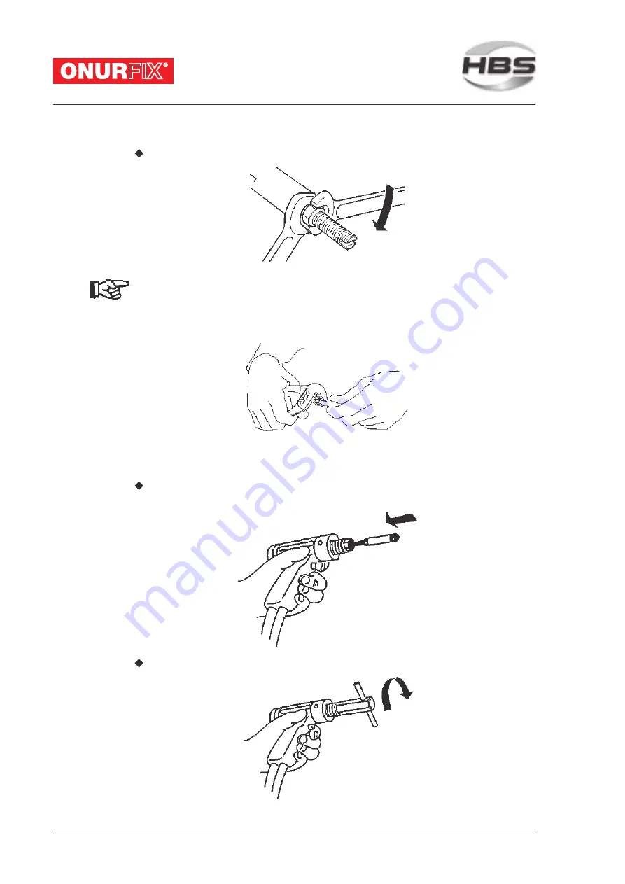
Retighten the retaining nut.

Retighten regularly and carefully the chuck at the four

segments (see figure below, at the visible end of the chuck)

using pliers to ensure a proper current transition. This will

prevent early wear through spark erosion.

4.3

Installation of Chuck

Put the chuck with loose retaining nut up to the stop into the piston of the

welding gun.

Tighten the retaining nut with the socket wrench SW 17.

Summary of Contents for 92-20-256

Page 1: ...C 08 Welding Gun 92 20 256 Operating Manual...

Page 2: ...e 18 85221 Dachau Germany Phone 49 0 8131 511 0 Fax 49 0 8131 511 100 E mail po hbs info com Web www hbs info com Copyright The information contained herein may not be copied reproduced adapted merged...

Page 3: ...malfunction In case of accident inform a physician and the responsible o cial body THREATTOLIFE Persons tted with a pace maker mu not operate the ud welding machine MAGNETICFIELDS During ud welding r...

Page 4: ...re copies please provide the order number li ed in the foot line Importantreminder Dataandinformationhereinwerecollectedwithgreate care Althoughwedidourvery be tocorrectlyupdateanyinformationuptotheti...

Page 5: ...the Power Unit 15 3 3 Ground Connection 16 3 4 Change Working Place 17 4 Function 18 4 1 Components of the Welding Gun 18 4 2 Adju ment of Chuck 19 4 3 In allation of Chuck 20 4 4 Adju ment of Spring...

Page 6: ...osal 36 7 Care and Maintenance 37 7 1 Safety In ructions 37 7 2 Regular Maintenance Operations 38 8 Appendix 39 8 1 Technical Data 39 8 2 Spare Parts 40 8 3 Accessories 42 8 4 Environmentally Admissib...

Page 7: ...safety in ructions Before arting up the welding gun let the operator sign the con rmation that he she has read and fully under ood the operating manual see appendix Do not commence ud welding until y...

Page 8: ...Welding Gun in Chapter 6 CareandMaintenance in Chapter 7 Technical Data and much more in the Appendix THREAT TO LIFE and risk of serious health and material damage in case of improper use of the weld...

Page 9: ...al mean Threat to life or risk of personal injury Risk of material damage Ban for persons tted with a pace maker Warning of dangerous electrical voltage Warning of electromagnetic elds Wear protective...

Page 10: ...ments according to actual andards see chapter 5 and appendix Any other use is regarded as not used as directed The manufacturer is not liable for damages resulting from the ud welding unit not used as...

Page 11: ...ing of the welding gun can only be checked before arting up by visual inspection visibledamage The following items are to be observed if the welding gun is not to be put into operation immediatelyafte...

Page 12: ...isible Type plate The type plate contains the following data Manufacturer Type OrderNo SerialNo Primaryvoltage Fuse Powerconsumption Cooling class Protection class Date Safety symbols Replace illegibl...

Page 13: ...2 20 256 Issue 01 03 08 13 2 Delivery The basic equipment of your welding gun contains the following components No of pieces Part Type OrderNo 1 Gun cable length 6 5 m C 08 92 20 256 1 Operatingmanual...

Page 14: ...x Weld only in adequate di ance from combu ible articles or liquids Before you art welding remove any combu ible articles or liquids in vicinity of the workplace Make sure that a re extinguisher is wi...

Page 15: ...spatters possibly liquid spatters a ash and a loud bang 90 dB A Alert any colleagues who are occupied in the vicinity of the welder Wear your personal protective equipment according to actual andards...

Page 16: ...cables Strong magnetic elds occur during welding which may cause a movement of the cables This may cause a slackness of the connections 3 3 Ground Connection Plug the ground cable in the connector of...

Page 17: ...between the two ground clamps 3 4 Change Working Place Switch o the power unit In this way you avoid any risk of electrical shock When you move your workplace disconnect the welding gun and the groun...

Page 18: ...ected through the welding gun handle to the welding gun Positioned at the front of the welding gun are the welding pi on and the retaining nut 3 used to x the manual chuck At the front of the welding...

Page 19: ...en the retaining nut Twi the op pin in the chuck in a way that the unthreaded part of the pin is inside the chuck for welding elements up to 20 mm length the unthreaded part of the pin projects is out...

Page 20: ...ur segments see gure below at the visible end of the chuck using pliers to ensure a proper current transition This will prevent early wear through spark erosion 4 3 In allation of Chuck Put the chuck...

Page 21: ...ng lines up with the 0 marking of the adju ment piece spring force Now rotate the adju ment piece spring force to the selected reference value table in chapter 5 to determine the spring pre tensioning...

Page 22: ...cal shock and arc During the actual ud welding process do not touch the welding elements chuck or retaining nut nor any electrically conductive parts in their vicinity These are all electrically life...

Page 23: ...s see appendix non combu ibleclothes ear protection to current andards see appendix a protective apron over your clothes a protective headgear when welding overhead Before arting to weld remove all co...

Page 24: ...ers a ash and a loud bang 90 dB A Alert any colleagues who are occupied in the vicinity of the welder Wear your personal protective equipment according to actual andards see appendix MAGNETIC FIELDS D...

Page 25: ...pring the welding element moves to the workpiece with a speed of 0 5 to 1 m s The adju ed spring force controls the plunging speed of the weldingelement Higher plunging speed leads to shortened arc ti...

Page 26: ...rom the weld zone and the ground clamp connectionareas paint oil and any other impurities ru non conductivecoatingsfromsurfacetreatedworkpieces Weld to smooth and at surfaces only For welding to pipes...

Page 27: ...5 mm 3 16 10 32 7 160 6 S235 M6 6 mm 1 4 1 4 20 9 200 6 1 4301 1 4303 M3 3 mm 1 8 6 32 2 60 6 1 4301 1 4303 M4 4 mm 5 32 8 32 3 70 6 1 4301 1 4303 M5 5 mm 3 16 10 32 4 5 100 6 1 4301 1 4303 M6 6 mm 1...

Page 28: ...ear always your personal protective equipment according to actual andards see appendix Insert the welding element into the chuck As soon as the power unit is ready for the welding process place the we...

Page 29: ...s The weld pool forms a collar around the flange of about 1 1 5 mm Correct parameters None Cold weld pool Gap between flange and workpiece Heat input too low Plunging speed too low No sufficient backi...

Page 30: ...directions The bending te is passed if a crack or a fracture of the welded zone does not occur Please note the in ructions on malfunctions and corrective actions in chapter 5 You don t need to te all...

Page 31: ...tal Heat input too low Plunging speed too low Welding element base material combination not suitable Increase charging voltage Increase plunging speed Replace welding element or workpiece Backside def...

Page 32: ...ction of the arc It causes a single sided melting of the ud material increased pore formation and undercuts in the weldingarea The arc blow e ect is proportional to the current and can be in uenced by...

Page 33: ...d 4 of the control cable socket w ith pressed w elding gun trigger In case of no flow Replace control cable Qualified personnel Trigger sw itch defective w ith present contact signal on pow er unit Ch...

Page 34: ...welding elements especially of the ignition tip require modi ed settings of the welding process Threaded ud PT Diameter Length Stud M3 6 30mm 82 50 003 M4 6 40mm 82 50 004 M5 8 45mm 82 50 005 M6 8 55...

Page 35: ...4 8 1 4301 1 4303 ISO clips for nails 2 3 Materials St2k70 galvanized 1 4301 1 4303 ISO clips for nails pla ic coated 3 Material St2k70galvanized Welookforwardtoconsultyouwithviewtospecialweldingeleme...

Page 36: ...y 6 1 Temporary Switching o Switch o the power unit Unplug the control cable and the welding cable from the welding gun Protect the welding gun again ingress of uids and foreign bodies 6 2 Disposal If...

Page 37: ...de long life expectancy 7 1 Safety In ructions Let maintenance and repair operations be carried out only by quali ed personnel or by your competent service technician Before you art any cleaning and m...

Page 38: ...nect control cable and welding cable from power unit Clean the surface of the welding gun of dirt and du Do not use any solvent containing cleaning agents Solvent containing cleaning agents may damage...

Page 39: ...er dimensions on reque Stud length 6 to 40 mm 0 24 to 1 57 longer uds can be welded with optional accessories Stud material Mild eel ainless eel Stud type Any type or shape special chucks if required...

Page 40: ...i on contact complete 31 1 80 09 765 Pressure spring contact 35 1 80 09 022 Axial arre 37 1 88 10 678A Adju mentpiecespringforcecomplete 39 1 80 11 272 Sticker spring force 41 1 88 10 879 End ring 49...

Page 41: ...C 08 Order No BA 92 20 256 Issue 01 03 08 41 Welding gun type C 08 92 20 256...

Page 42: ...un for Description Order No Socket wrench 80 40 085 Chuck Threaded udPT M2 82 50 002 M2 5 82 50 025 M3 82 50 003 M4 82 50 004 M5 82 50 005 M6 82 50 006 M8 82 50 008 M10 82 50 009 PinUT 3 mm 82 50 003...

Page 43: ...2 20 256 Issue 01 03 08 43 for Description Order No Chuck Flat pin 6 3 mm 82 50 050 Double at pin Chuck ISO nail 2 mm 82 50 020 3 mm 82 50 030 Weldingofwelding Angle PWA 82 40 011 elements up to 8 5 m...

Page 44: ...g or Noise damping tube PSR2 protect again droppingwelding spatters 35 mm 82 40 016 ISO nails Tripod with 3 point re PSI2 100 to 300 mm length 92 40 043 weldingelements from 40 mm length PSI2 3 point...

Page 45: ...elding templates with cylinder pin centering pot and chuck extension 20 mm 92 40 111 26 mm 92 40 117 30 mm 92 40 119 PZV2 Centering tube 20 mm 80 40 082 26 mm 80 40 086 30 mm 80 40 083 PZV2 Centering...

Page 46: ...ue 01 03 08 for Description Order No Weldingelements Di ance ring 16 mm 92 40 010 40 to 56 mm length Foot ring Foot 6 mm 80 40 049 6 mm with hard tip 80 40 076 Pitch circle Foot ring TK38 80 40 521 di...

Page 47: ...appendix including a set of bushings for 3 8 mm Bending device 80 40 120 including equipment to eject uptight uds withoutbushings Bushing for bending device for welding elements M3 80 40 121 for weldi...

Page 48: ...20 256 Issue 01 03 08 8 4 Environmentally Admissible Disposal After repair of the welding gun dispose replaced parts in an environmentally admissible way Used materials Steel Nonferrousmetals brass c...

Page 49: ...ent Studfeeder Devicefortheautomatic udfeedingofweldingelements Stud welding unit Power unit inclusive welding gun Thyri or Electronic component contactless switch which will let the current only pass...

Page 50: ...welding method for metals General DVS0902 Drawn arc udwelding DVS0903 Capacitor discharge ud welding with tip ignition DVS0904 In ructions for practice Arc ud welding DVS2927 Resi or projection weldi...

Page 51: ...ompatiblity EMC requirements Personalsafetyandaccidentprevention DIN EN ISO 20345 Personalprotectiveequipment Safetyfootwear DINEN12477 Protectiveglovesforwelders DIN EN 166 Personal eye protection Sp...

Page 52: ...4 81 0 18 Rp0 2 340 N mm2 1 4301 03 A2 50 0 18 Rp0 2 210 N mm2 AlMg3 F23 0 18 Rp0 2 170 N mm2 CuZn37 Ms63 0 18 Rp0 2 250 N mm2 Values correspond with actual standards 1 weldable All given values are...

Page 53: ...lledifrepairoperationsarecarriedoutbyunauthorized persons Warning Unauthorized interference with the ud welding unit as well as unauthorized alteration of the ud welding unit are prohibited and result...

Page 54: ...approval by HBS Description of equipment Welding Gun Type C 08 Order No 92 20 256 Serial No Applicable EC guidelines and corresponding andards Low voltage guideline 2006 95 EC DIN EN 60974 1 Arc weldi...

Page 55: ...__________________ ________________ ___________________________________ ________________ ___________________________________ ________________ ___________________________________ ________________ _____...

Page 56: ..._______________ 85221 Dachau Germany __________________________ Po fach 13 46 __________________________ 85203 Dachau Germany __________________________ Productdescription __________________________ S...

Page 57: ...C 08 Order No BA 92 20 256 Issue 01 03 08 57 Service Support...

Page 58: ...7 company speci c work order 7 components of the welding gun 18 con rmation 55 con rmation operator sign 7 contact ud welding 25 control cable connector 16 D delivery 8 13 disposal 36 48 di ance devic...

Page 59: ...operation improper 28 operators 7 order number 40 P pace maker 9 15 24 personnel 7 pin UT 34 pin with internal thread IT 34 pipes welding to 26 place of operation 10 pla ic housing 18 plunging speed 2...

Page 60: ...ue 27 52 training according to current andards 7 transportation 7 transportation packaging orage 11 tripod with 3 point rest 44 type plate 12 U unauthorized use 7 user quali cation required 7 UT pin 2...

Page 61: ......

Page 62: ...HBS Bolzenschweiss Sy eme GmbH Co KG Felix Wankel Strasse 18 85221 Dachau Germany Phone 49 0 8131 511 0 Fax 49 0 8131 511 100 E mail po hbs info com www hbs info com...

Reviews: