11
VKK14 / VKK1
R
4
A23261.0 en/de/fr
H
BM
4
C
onnection
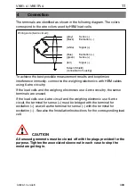
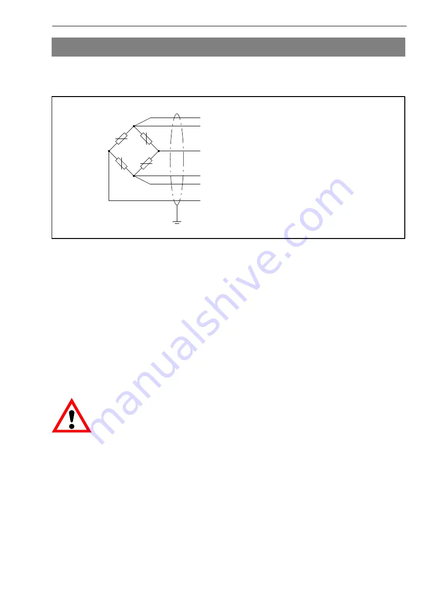
The terminals are identified as sho
w
n in the follo
w
ing diagram. The colors
correspond to the
w
ire colors used by
H
BM load cells.
(
w
hite)
(black)
(gray)
Excitation (+)
(green)
(red)
Excitation (−)
Sense (−)
Signal (+)
(blue)
Sense (+)
Signal (−)
Screen (Shield)
(connected to housing)
Wiring code (6
w
ire circuit):
To achie
v
e the bestpossible measurement results and to optimize
interference immunity, connect to the
w
eighing electronics
w
ith
H
BM cables
using 6
w
ire circuitry.
If the load cells and the
w
eighing electronics use 4
w
ire circuitry, the sense
terminals are unused.
If the load cells use 4
w
ire circuit and the
w
eighing electronic use 6
w
ire
circuit, the terminal for sense (+) must be bridged
w
ith the terminal for
excitation (+) as
w
ell as the terminal for sense (−)
w
ith the terminal for
excitation (−). See also the Installation Instructions for the corresponding load
cell.
C
AUTION
All unused g
r
ommets must be closed off with the plugs p
r
ovided fo
r
the
pu
r
pose. Tighten the associated sleeve nut in each case to stop the
moistu
r
e getting in.


