background image

Safety instructions

8

A02590_04_E00_00


HBM: public

TIM40

S

As automation plant operating personnel, you have been instructed how to
handle the machinery and are familiar with the operation of the equipment
and technologies described in this documentation.

S

As commissioning engineers or service engineers, you have successfully
completed the training to qualify you to repair the automation systems. You
are also authorized to activate, to ground and label circuits and equipment
in accordance with safety engineering standards.

It is also essential to comply with the legal and safety requirements for the ap­
plication concerned during use. The same applies to the use of accessories.

Summary of Contents for TIM40

Page 1: ...Mounting Instructions English TIM40...

Page 2: ...3 0 Fax 49 6151 803 9100 info hbm com www hbm com Mat DVS A02590_04_E00_00 HBM public 10 2021 E Hottinger Br el Kjaer GmbH Subject to modifications All product descriptions are for general information...

Page 3: ...9 Electrical connection 21 9 1 General information 21 9 2 Shielding design 21 9 3 Connector pin assignment 21 9 3 1 Connect cable wires to spring loaded terminals 23 9 4 Supply voltage 25 9 5 Connecti...

Page 4: ...tioning 34 12 1 12 Save load parameters 34 12 1 13 Measuring 35 13 Interface description 36 13 1 CANopen 36 13 1 1 Connection 36 13 1 2 LED status display 38 13 1 3 Cyclic transmission of measured val...

Page 5: ...ust first run a project planning and risk analysis that takes into account all the safety aspects of automation technology This particularly concerns personal and machine protection Additional safety...

Page 6: ...ay that malfunctions in individual nodes can be detected and shut down Safety precautions must be taken both in terms of hardware and software so that a line break or other interruptions to signal tra...

Page 7: ...fety engineering point of view except with our express agreement Any modification shall exclude all liability on our part for any damage resulting therefrom In particular any repair or soldering work...

Page 8: ...documentation S As commissioning engineers or service engineers you have successfully completed the training to qualify you to repair the automation systems You are also authorized to activate to grou...

Page 9: ...sult in slight or moderate physical injury Notice This marking draws your attention to a situation in which failure to comply with safety requirements can lead to damage to property Important This mar...

Page 10: ...ation of conformity is avail able at http www hbm com HBMdoc Statutory marking requirements for waste disposal National and local regulations regarding the protection of the environment and recycling...

Page 11: ...3 Scope of supply S 1 TIM40 Torque Interface Module S Connector for transducer connection S Connector for frequency output S Connector for analog outputs S Connector for shunt signal triggering S Conn...

Page 12: ...ce digital measurement signals of the torque flange T40 The signals can be filtered scaled and output at the analog outputs as current voltage or frequency signals The measure ment signals are also av...

Page 13: ...e measurement data of the T40 stator 38 125 measured values s 16 Bit at input X3 Two deactivatable digital filters 1 are available for all subsequent signal routes and scaling 2 for each output Scalin...

Page 14: ...s mounted on a DIN EN 60715 rail A spring on the back holds the housing in position Spring Fig 6 1 Housing back Hook the interface module into the upper guide of the rail Press the housing against the...

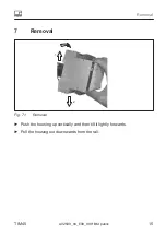
Page 15: ...Removal TIM40 A02590_04_E00_00 HBM public 15 7 Removal 1 2 Fig 7 1 Removal Push the housing up vertically and then tilt it lightly forwards Pull the housing out downwards from the rail...

Page 16: ...ule TIM40 has a slot for Anybus modules Notice Take care when mounting the module If the module is askew the connection pins inside the housing may get bent Place the TIM40 housing on a flat surface a...

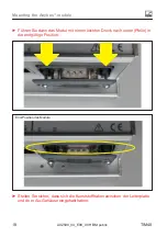
Page 17: ...tage mit Anybus Modul Important Achten Sie bitte darauf dass die Befestigungsschrauben am Anybus Modul vor der Montage min 1 cm heraus geschraubt sind und die Arretierung Pfeil nicht heraus ragt Schie...

Page 18: ...HBM public TIM40 F hren Sie dann das Modul mit einem leichten Druck nach unten Pfeile in die endg ltige Position End Position des Moduls Stellen Sie sicher dass sich die Kunststoffhaken zwischen der L...

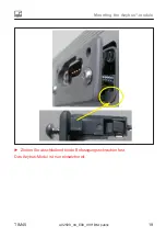
Page 19: ...Mounting the Anybus module TIM40 A02590_04_E00_00 HBM public 19 Ziehen Sie abschlie end beide Befestigungsschrauben fest Das Anybus Modul ist nun einsatzbereit...

Page 20: ...ully into the housing When the module protrudes approx 1 cm from the housing you will feel a resistance see Fig 8 3 The module will now be centered by the side grooves Carefully push the module into t...

Page 21: ...tors thyristor controls and similar stray field sources 9 2 Shielding design The cable shield should be connected to the protective housing according to the Greenline concept This encloses the measure...

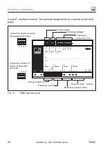
Page 22: ...d on the front panel Voltage supply Shunt signal trigger Transducer connection T40 4 3 2 1 Connection position of upper spring loaded terminals 1 2 3 4 Connection position of lower spring loaded termi...

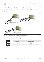
Page 23: ...can connect wires with a cross section of maximum 0 5 mm2 to the spring loaded terminals 1 Press and hold down spring pin 2 Insert bared cable wire fitted with end sleeve 3 Release spring pin Fig 9 2...

Page 24: ...ment 1 0 V 2 5 24 V Connection X3 for torque measurement flange T40 4 3 2 1 8 7 6 5 Terminal Assignment Color code KAB174 1 RS422 RA rd 2 RS422 RB wh 3 DGND vt 4 RS232 RX gn 5 RS232 TX gy 6 0 V bu 7 2...

Page 25: ...ted extra low voltage sup ply voltage 18 to 30 V DC The supply voltage lead must be no more than 3 m long Connecting to a direct voltage network in accordance with EN 61326 is not permitted Instead us...

Page 26: ...r the con nection 9 5 1 Single connection to PC laptop T40 TIM40 UPnP active DHCP active PC laptop DHCP active Fig 9 3 Example Direct connection to PC laptop In normal cases TIM40 is automatically det...

Page 27: ...1 1 in the IP address line the subnet mask is automatically set to 255 255 255 0 Confirm twice with OK Update the view by pressing the function key F5 Double clicking on the TIM40 symbol opens the TIM...

Page 28: ...rk environment with a double click Various options can be seen under Network tasks in the opened window This should include the option Hide Network UPnP device symbols If not you can activate the opti...

Page 29: ...r triggering the shunt signal is 5 V triggering at U 2 5 V The trigger voltage is electrically isolated from the supply volt age and the measurement voltage The maximum permissible voltage is 36 V Whe...

Page 30: ...alues Green Transmission of measured values OK Red Transmission of measured values not OK Flashing red Parameter inconsistent or incorrect Link Link status Green Link status Act Ethernet communication...

Page 31: ...b browser we recommend Microsoft Internet Explorer when connected via Ethernet 12 1 Settings with the web browser Start the web browser by double clicking on the TIM40 symbol in the network environmen...

Page 32: ...scode In delivery condition no passcode is active 12 1 4 System Ethernet interface You can find your Ethernet connection data here and can switch the DHCP Client on off You can select the signal and s...

Page 33: ...n also activate two low pass filters 1 Hz to 3 KHz 12 1 9 Transducer parameterization Frequency output Select the signal at the frequency output low pass 1 or 2 and the required output frequency 10 5...

Page 34: ...que transducer e g 3 kN m to 3 kN m 3 000 N m 12 1 11 Signal conditioning You can connect a shunt and carry out a zero balance We recommend zero ing only in the range within 10 of the nominal rated me...

Page 35: ...02590_04_E00_00 HBM public 35 12 1 13 Measuring You can read the possibly filtered but unscaled raw measured values of both signals here which are also unaffected by a zero balance The sampling rate i...

Page 36: ...as a slot for an Anybus CC CANopen module over which both measured values can be transmitted and simple parameteriza tion of the module can be implemented see 13 1 4 RPDO1 Different baud rates can be...

Page 37: ...E00_00 HBM public 37 Connector pin assignment 5 1 9 6 Top view LED RUN LED ERROR Pin Assignment 1 No function 2 CAN LOW 3 CAN GND 4 No function 5 Shielding connected to enclosure groun 6 No function 7...

Page 38: ...Warning limit reached Red flickering LSS Red flashing 2x Error control event Red1 Bus off fatal event 1 If both LEDs are red this indicates a serious error the bus interfaces are physically switched t...

Page 39: ...ation TPDO1 packets are only transmitted from the TIM40 when the measured value has changed TPDO2 Status CAN Identifier COB ID 640 280h CAN address Data 1 2 data byte Status Status Status Byte Meaning...

Page 40: ...o function 1 zeroing of actual measured value Torque zeroing 1 0 Reserved 2 0 Shunt off 1 Shunt on Activate shunt calibration 3 5 0 Reserved 6 7 00 Parameter set 1 01 Parameter set 2 10 Parameter set...

Page 41: ...data byte Module address 0 ID 110 6e hex 13 1 6 Parameterization Messages for module parameterization are transmitted as so called Service Data Objects SDOs in accordance with CANopen definitions The...

Page 42: ...byte 66 42Hex 2 3 data byte Index LSB MSB 4 data byte Sub index 5 8 data byte Value LSB MSB Writing a parameter Transmit value PC or PLC to TIM40 CAN Identifier 1536 600 Hex module address 1 data byt...

Page 43: ...2 PROFIBUS 13 2 1 Connection The TIM40 interface module has a slot for an Anybus PROFIBUS module over which both measured values can be transmitted and simple parameteriza tion of the module can be i...

Page 44: ...ignment 1 5 6 9 Top view LED Operation Mode LED Status Pin Assignment 1 No function 2 No function 3 Data line B RxD TxD minus RS 485 4 RTS 5 GND Bus 6 5 V Bus output 7 No function 8 Data line A RxD Tx...

Page 45: ...ion error Red flashing 2x Profibus configuration error LED Status H2 Color status Meaning Off No voltage supply or no initialization Green Initializing complete Red Exception error 13 2 3 Cyclic data...

Page 46: ...sers S To transmit consistent data you must use the special function blocks SFC14 to read and SFC15 to write S With S7 3xx a maximum of 32 bytes of consistent data can be transmitted The TIM40 allows...

Page 47: ...ement 32 bit quantities 4 bytes To obtain the measured value in the physical quantity for displaying n decimal places divide by 10n The byte sequence corresponds to the Profibus standard in that it al...

Page 48: ...48 A02590_04_E00_00 HBM public TIM40 Bit 6 Bit 7 1 0 Parameter set 3 1 1 Parameter set 4 The function Load parameter set is only implemented when the new parame ter set number differs from the actual...

Page 49: ...d in object 2120 Hex Alternatively these quantities are also available as Float values IEEE754 1985 32 bit format HBM T12 Object Dictionary Index hex Sub Ix Attr Format Name 1008 0 RO VISIBLE STRING M...

Page 50: ...Maintenance 50 A02590_04_E00_00 HBM public TIM40 15 Maintenance The torque interface module TIM40 is maintenance free...

Page 51: ...l input shunt Input level On V 2 5 Input level Off V 1 5 Max input voltage V 36 Max input current at 24 V mA 24 Outputs Frequency output Nominal rated output signal at 10 kHz 60 kHz 240 kHz kHz kHz kH...

Page 52: ...t frequency range 3 dB Hz 0 8000 Burden W v 500 Digital low pass filter Bessel can be switched off Low pass filter TP 1 1 dB Hz 1 10 100 1000 3000 Low pass filter TP 2 1 dB Hz 1 10 100 1000 3000 1 Fac...

Page 53: ...ine length m 5000 2500 1000 500 500 250 100 50 25 Profibus DP Protocol Profibus DP Slave according to DIN 19245 3 Max update rate Mv s 1000 Baud rate MBaud max 12 Environmental requirements Degree of...

Page 54: ...mber of impacts n 3 in each direction Duration ms 11 Acceleration half cosine m s2 200 EMC requirements EMC According to EN 61326 2006 industrial environment Emission EME DIN EN 61326 2006 Class A Imm...

Page 55: ...Dimensions TIM40 A02590_04_E00_00 HBM public 55 17 Dimensions 136 1 97 15 23 3 169 88 7 57 45 41 45 10 23 10 23 105 4 45 5 70 9 73 5 42 5 75 4 Dimensions in mm 1 mm 0 03937 inches...

Page 56: ...onnection cable ready made Connection cable TIM40 Binder 423 16 pole free ends 6 m 1 KAB174 6 Protective housing for TIM40 protection class IP67 9 screwed cable glands clamping range 4 5 mm 10 mm 3 64...

Page 57: ...00_00 HBM public 57 181 5 200 9 25 6 4 300 235 4 32 3 62 5 31 25 120 50 25 25 56 25 87 5 118 75 150 181 25 212 5 243 75 275 25 Protective housing 9 x PG9 screwed cable glands for cable 4 8 mm Dimensio...

Page 58: ...www hbm com HBM Test and Measurement Tel 49 6151 803 0 Fax 49 6151 803 9100 info hbm com measure and predict with confidence A02590_04_E00_00 HBM public...

Reviews: