


11
PWSE
A3361-1.0 en/de/fr
HBM
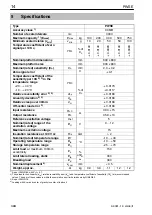
4
Electrical connection
The following can be connected for measurement signal conditioning:
Carrier‐frequency amplifier
DC amplifier
designed for strain gauge measurement systems.
The transducers are supplied in the standard version with a 3m cable and
6‐pin Pancon connector in a six‐wire configuration.
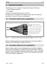
4.1
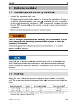
Connection with six‐wire configuration
4
Plug‐in contact 1 (white) = measurement signal (+)
Plug‐in contact 3 (black) = excitation voltage (-)
Plug‐in contact 6 (gray) = sense lead (-)
Plug‐in contact 4 (blue) = excitation voltage (+)
Plug‐in contact 5 (green) = sense lead (+)
Plug‐in contact 2 (red) = measurement signal (-)
Schematic diagram of a Pancon connector (CE100F26‐6), 6‐pin
1
2
3
5
6
blue marking
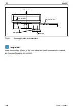
Shield (yellow) = cable shield connected to
load cell body
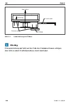
Fig. 4.1:
Connection with a 6‐wire cable (choice of lengths: 3m, 6m or 12m)
With this cable assignment, the output voltage at the measuring amplifier is
positive when the transducer is loaded (see Fig.3.1).
4.2
Connection with four‐wire configuration
When transducers with a six‐wire configuration are connected to amplifiers
with a four‐wire configuration, the sense leads of the transducer must be con
nected to the corresponding supply leads: Identification (+) with (+) and identi
fication (-) with (-), see Fig. 4.1. This measure also reduces the cable resist
ance of the excitation voltage leads.
Summary of Contents for PWSE
Page 2: ...English Page 3 13 Deutsch Seite 14 24 Fran ais Page 25 32...
Page 16: ...PWSE 16 A3361 1 0 en de fr HBM...
Page 30: ...PWSE 30 A3361 1 0 en de fr HBM...
Page 45: ...45 PWSE A3361 1 0 en de fr HBM...
Page 46: ...PWSE 46 A3361 1 0 en de fr HBM...
Page 47: ......