background image

Markings used

6

A03009_02_Y00_01


HBM: public

PW25…

2

Markings used

2.1

The markings used in this document

Important instructions for your safety are specifically identified. It is essential to
follow these instructions in order to prevent accidents and damage to property.

Symbol

Significance

CAUTION

This marking warns of a 

potentially

 dangerous situa­

tion in which failure to comply with safety require­
ments 

can

 result in slight or moderate physical injury.

Notice

This marking draws your attention to a situation in
which failure to comply with safety requirements 

can

lead to damage to property.

Important

This marking draws your attention to 

important

 infor­

mation about the product or about handling the prod­
uct.

Tip

This marking indicates application tips or other infor­
mation that is useful to you.

Information

This marking draws your attention to information
about the product or about handling the product.

Emphasis
See…. 

Italics are used to emphasize and highlight text and
references to other chapters and external documents.

Summary of Contents for PW25

Page 1: ...Mounting Instructions Montageanleitung Notice de montage English Deutsch Français PW25 ...

Page 2: ...All product descriptions are for general information only They are not to be understood as a guarantee of quality or durability Änderungen vorbehalten Alle Angaben beschreiben unsere Produkte in allgemeiner Form Sie stellen keine Beschaffenheits oder Haltbarkeits garantie dar Sous réserve de modifications Les caractéristiques indiquées ne décrivent nos produits que sous une forme générale Elles n ...

Page 3: ...Mounting Instructions Montageanleitung Notice de montage English Deutsch Français PW25 ...

Page 4: ...2 2 Symbols on the product 7 3 Mounting and load application 8 4 Electrical connection 9 4 1 Connecting in four wire and six wire configurations 9 4 2 Cable protection provided by customer 10 4 3 Shortening the cable 10 4 4 Cable extension 10 4 5 Parallel connection 11 4 6 EMC protection 11 5 Specifications 12 6 Dimensions 12 ...

Page 5: ...structions It is also essential to comply with the legal and safety requirements for the application concerned during use The same applies to the use of accessories Load cells can be used as machine elements for tank weighing for example In these situations you must make sure that for greater sensitivity the load cells are not constructed with the customary safety factors found in machine design L...

Page 6: ...ld there be any corrosion this could cause the load cell to fail If this is the case the operator must take appropriate protective measures Unauthorized conversions and modifications are prohibited Load cells must not be modified from the design or safety engineering point of view except with our express agreement Any modification shall exclude all liability on our part for any damage resulting th...

Page 7: ...a from the specifications S limit load EL S limit load at max eccentricity S limit lateral loading ELq S breaking load Load cells are precision measuring elements and must be handled carefully during mounting and transportation Knocking or dropping the load cells can damage them Suitable retainers must be used during installation and operation to protect the load cells against overloading No force...

Page 8: ...sult in slight or moderate physical injury Notice This marking draws your attention to a situation in which failure to comply with safety requirements can lead to damage to property Important This marking draws your attention to important infor mation about the product or about handling the prod uct Tip This marking indicates application tips or other infor mation that is useful to you Information...

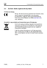
Page 9: ...n of conformity is avail able at http www hbm com HBMdoc Statutory marking requirements for waste disposal National and local regulations regarding the protection of the environment and recycling of raw materials require old equipment to be separated from regular domestic waste for disposal If you need more information about waste disposal please contact your local authorities or the dealer from w...

Page 10: ... thread reach Min property class Tightening torque1 Standard M6 10 mm 8 8 10 N m Rustless M6 10 mm A2 70 or A4 70 10 N m 1 Recommendedvalue for the specified property class Please comply with the screw manufacturer s instructions with regard to screw dimensions Load must not be applied to the side where the cable connection is located as this would cause a force shunt Load application platform cen...

Page 11: ...ells using a six wire configuration are connected to amplifiers with a four wire configuration the sense leads of the load cells must be connected to the corresponding supply leads marking with and marking with 6 wire cable connection 4 Contact 1 white Signal Contact 3 black Excitation Contact 6 gray Sense Contact 4 blue Excitation Contact 5 green Sense Contact 2 red Signal Shield yellow cable shi...

Page 12: ...9K degree of protection In applications where the PUR cable of the load cell can be chemically or mechanically attacked or destroyed extra cable protection can be provided by means of standard cable protection systems 4 3 Shortening the cable As the load cell connection uses a six wire configuration you can shorten the 6 wire load cell cable without this changing the load cell calibration 4 4 Cabl...

Page 13: ... cables fulfill both conditions S Do not route the measurement cables parallel to power lines and control circuits If this is not possible protect the measurement cable in rigid steel conduits for example S Avoid stray fields from transformers motors and contact switches To ensure the best EMC protection the load cell together with the connection cable and the subsequent electronics should be plac...

Page 14: ...lic PW25 5 Specifications Information Further product information can be found at www hbm com pw 6 Dimensions 6 M6 19 0 1 100 0 2 19 0 1 M6 35 68 35 150 0 2 14 5 24 9 14 32 5 35 35 32 5 Ø40 10 10 30 0 1 55 5 Dimensions in mm 1 mm 0 03937 inches ...

Page 15: ...Mounting Instructions Montageanleitung Notice de montage English Deutsch Français PW25 ...

Page 16: ... Kennzeichnungen 6 2 2 Auf dem Gerät angebrachte Symbole 7 3 Montage und Lasteinleitung 8 4 Elektrischer Anschluss 9 4 1 Anschluss in Vier und Sechsleiter Technik 9 4 2 Kabelschutz kundenseitig vorzusehen 10 4 3 Kabelkürzung 10 4 4 Kabelverlängerung 10 4 5 Parallelschaltung 11 4 6 EMV Schutz 11 5 Technische Daten 12 6 Abmessungen 12 ...

Page 17: ...zusätzlich die für den jeweiligen Anwendungsfall erforderlichen Rechts und Sicherheitsvorschriften zu beachten Sinngemäß gilt dies auch bei der Verwendung von Zubehör Die Wägezellen können als Maschinenelemente z B bei Behälterverwie gungen eingesetzt werden Beachten Sie in diesen Fällen dass die Wäge zellen zugunsten einer hohen Messempfindlichkeit nicht mit den in Maschinen konstruktionen üblich...

Page 18: ...Verbot von eigenmächtigen Umbauten und Veränderungen Die Wägezellen dürfen ohne unsere ausdrückliche Zustimmung weder kon struktiv noch sicherheitstechnisch verändert werden Jede Veränderung schließt eine Haftung unsererseits für daraus resultierende Schäden aus Qualifiziertes Personal Die Wägezellen sind nur von qualifiziertem Personal ausschließlich entspre chend der technischen Daten in Zusamme...

Page 19: ... max Exzentrizität S Grenzquerbelastung ELq S Bruchlast Als Präzisions Messelement sind Wägezellen bei der Montage und beim Transport sorgfältig zu behandeln Stöße oder Fallenlassen können die Wäge zellen beschädigen Bei Einbau und Betrieb sind die Wägezellen durch geeignete Anschläge vor Überlastung zu schützen Bei der Montage dürfen keine Kräfte und Momente über das Federelement geleitet werden ...

Page 20: ...ttlere Körperverletzung zur Folge haben kann Hinweis Diese Kennzeichnung weist auf eine Situation hin die wenn die Sicherheitsbestimmungen nicht beachtet werden Sachschäden zur Folge haben kann Wichtig Diese Kennzeichnung weist auf wichtige Informa tionen zum Produkt oder zur Handhabung des Pro duktes hin Tipp Diese Kennzeichnung weist auf Anwendungstipps oder andere für Sie nützliche Informatione...

Page 21: ...lärung finden Sie auf der Website von HBM www hbm com unter HBMdoc Gesetzlich vorgeschriebene Kennzeichnung zur Entsorgung Nicht mehr gebrauchsfähige Altgeräte sind gemäß den nationalen und örtlichen Vorschriften für Umweltschutz und Rohstoffrückgewinnung getrennt von regulärem Hausmüll zu entsorgen Falls Sie weitere Informationen zur Entsorgung benö tigen wenden Sie sich bitte an die örtlichen Be...

Page 22: ... Max Einschraubtiefe Min Festigkeits klasse Anzugs moment1 Standard M6 10 mm 8 8 10 N m Rostfrei M6 10 mm A2 70 oder A4 70 10 N m 1 Richtwert für die angegebene Festigkeitsklasse Zur Auslegung von Schrauben beachten Sie bitte die entsprechenden Informationen der Schraubenhersteller Die Lasteinleitung darf nicht auf der Seite des Kabelanschlusses erfolgen dies führt zu einem Kraftnebenschluss Laste...

Page 23: ...r Technik ausgeführt sind an Verstärker mit Vierleiter Technik angeschlossen werden sind die Fühlerleitungen der Wägezellen mit den entsprechenden Speiseleitungen zu verbinden Kennzeichnung mit und Kennzeichnung mit Anschluss mit 6 adrigem Kabel 4 Kontakt 1 weiß Signal Kontakt 3 schwarz Speisung Kontakt 6 grau Fühler Kontakt 4 blau Speisung Kontakt 5 grün Fühler Kontakt 2 rot Signal Schirm gelb Ka...

Page 24: ...R Kabel der Wägezelle chemisch oder mechanisch angegriffen oder zerstört werden kann ist es möglich das Kabel mittels handelsüblicher Kabelschutzsysteme zusätz lich zu schützen 4 3 Kabelkürzung Da der Anschluss der Wägezelle in Sechsleiter Technik ausgeführt ist können Sie das 6 adrige Kabel der Wägezelle kürzen ohne dass dadurch die Kalibrierung der Wägezelle verändert wird 4 4 Kabelverlängerung ...

Page 25: ...l erfüllen diese Bedingungen S legen Sie die Messkabel nicht parallel zu Starkstrom und Steuerleitungen Falls das nicht möglich ist schützen Sie das Messkabel z B durch Stahl panzerrohre S meiden Sie Streufelder von Trafos Motoren und Schützen Um den besten EMV Schutz zu gewährleisten sollte die Wägezelle mit dem Anschlusskabel und der nachfolgenden Elektronik gemeinsam in einem geschirmten Gehäus...

Page 26: ...0_01 HBM public PW25 5 Technische Daten Information Weitere Produktinformationen unter www hbm com de pw 6 Abmessungen Abmessungenin mm 6 M6 19 0 1 100 0 2 19 0 1 M6 35 68 35 150 0 2 14 5 24 9 14 32 5 35 35 32 5 Ø40 10 10 30 0 1 55 5 ...

Page 27: ...Mounting Instructions Montageanleitung Notice de montage English Deutsch Français PW25 ...

Page 28: ... utilisés sur le produit 7 3 Montage et application de charge 8 4 Raccordement électrique 9 4 1 Raccordement en technique à quatre et six fils 9 4 2 Protection du câble à prévoir par le client 10 4 3 Raccourcissement de câble 10 4 4 Rallonges de câble 10 4 5 Branchement en parallèle 11 4 6 Protection CEM 11 5 Caractéristiques techniques 12 6 Dimensions 12 ...

Page 29: ...ute sécurité ceux ci doivent être utilisés conformément aux instructions de la notice de montage De plus il convient pour chaque cas particulier de respecter les règlements et consignes de sécurité correspondants Ceci s applique également à l utilisation des accessoires Les pesons peuvent être utilisés en tant qu éléments de machine p ex pour le pesage de cuves Dans ce cas noter que les pesons pou...

Page 30: ...r inoxydable il faut noter que les acides et toutes les substances libérant des ions attaquent également les aciers inoxydables et leurs cordons de soudure La corrosion éventuelle qui peut en résulter est susceptible d entraîner la défaillance du peson L exploitant doit donc prévoir des mesures de protection correspondantes Interdiction de procéder à des transformations et modifications sans accor...

Page 31: ...par les caisses professionnelles d assurance accident Respec ter en particulier les valeurs indiquées dans les caractéristiques techniques pour S la charge limite EL S la charge limite pour l excentricité max S la charge latérale limite ELq S la charge de rupture En tant qu élément de mesure de précision les pesons doivent être manipulés avec soin lors du montage et du transport Un choc ou une chu...

Page 32: ...eut avoir pour conséquence des blessures corporelles de gravité minime ou moyenne Note Ce marquage signale une situation qui si les dispositions relatives à la sécurité ne sont pas respectées peut avoir pour conséquence des dégâts matériels Important Ce marquage signale que des informations importantes concernant le produit ou sa manipulation sont fournies Conseil Ce marquage est associé à des con...

Page 33: ...rmité visitez http www hbm com HBMdoc Marquage prescrit par la loi pour la gestion des déchets Selon les règlements nationaux et locaux relatifs à la pro tection de l environnement et au recyclage des matières premières les anciens appareils doivent être séparés des déchets ménagers pour l élimination Pour plus d informations sur l élimination d appareils consultez les autorités locales ou le reve...

Page 34: ...e Longueur de filet max Classe de dureté min Couple de serrage2 Standard M6 10 mm 8 8 10 N m Inoxydable M6 10 mm A2 70 ou A4 70 10 N m 2 Valeur recommandée pour la classe de dureté indiquée Pour la taille des vis respecter les informations fournies par le fabricant de vis La charge ne doit pas être appliquée du côté du raccordement du câble afin d éviter tout shunt de force Applicationde charge ce...

Page 35: ...nt conçus en technique à six fils mais raccordés à un amp lificateur à quatre fils il est alors nécessaire de relier les fils de contre réaction des pesons aux fils d alimentation correspondants avec et avec Branchement avec un câble à 6 fils Contact 1 blanc signal Contact 3 noir alimentation Contact 6 gris contre réaction Contact 4 bleu alimentation Contact 5 vert contre réaction Contact 2 rouge ...

Page 36: ...applications où le câble PUR du peson peut être attaqué ou détruit par voie chimique ou mécanique il est possible d ajouter une protection supplémentaire grâce à des systèmes de protection de câble disponibles dans le commerce 4 3 Raccourcissement de câble Comme le peson est raccordé en technique six fils le câble à 6 fils du peson peut être raccourci sans que cela n affecte le calibrage du peson ...

Page 37: ...indés de faible capacité les câbles HBM satisfont à ces conditions S ne pas poser les câbles de mesure en parallèle avec des lignes de puissance et des lignes de contrôle Si ce n est pas possible protéger le câble de mesure p ex via des tubes d acier S éviter les champs de dispersion des transformateurs moteurs et vannes Pour garantir la meilleure protection CEM placer le peson le câble de liaison...

Page 38: ...M public PW25 5 Caractéristiques techniques Information Pour plus d informations sur les produits voir www hbm com fr pw 6 Dimensions Dimensions en mm 6 M6 19 0 1 100 0 2 19 0 1 M6 35 68 35 150 0 2 14 5 24 9 14 32 5 35 35 32 5 Ø40 10 10 30 0 1 55 5 ...

Page 39: ...Raccordement électrique PW25 A03009_02_Y00_01 HBM public 13 ...

Page 40: ...www hbm com HBM Test and Measurement Tel 49 6151 803 0 Fax 49 6151 803 9100 info hbm com measure and predict with confidence A03009_02_Y00_01 7 0101 0007 HBM public ...

Reviews: