


Inputs and outputs
18
A03924_02_YI0_00
HBM: public
FIT
®
7A
Valve 1
Valve 2
Power
supply 1
Power
supply 2
Connector 1
Connector 2
Connector 1
Connector 2
Ub 1
GND 1
Ub 2
GND 2
FIT7A - 1
FIT7A - 2
OUTx
OUTx
GND
connection
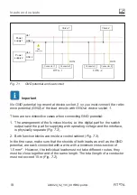
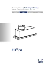
Fig. 7.1
GND potential and load circuit
Important
No GND potential is present at device socket 2, so you must connect the refer
ence potential (GND) of the load circuits with GND at device socket 1.
There are two distinctive cases when connecting GND potential:
1. The arrangement of the function blocks, i.e. the digital part for the switch
outputs and the part for supplying with operating voltage and the interface,
is physically separate (
).
2. Both function blocks are inside a control cabinet (
).
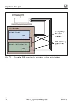
In the first case, make sure that the shields of both leads, as well as the GND
potential, are each connected with a wire with a minimum cross-section of
1.5 mm
2
. However, the individual leads must not take different routes, they
must be close together and of the same length. The total length of a conductor
must not exceed 10 m (


