background image

Operating Manual | Bedienungsanleitung |
Manuel d'emploi

English

Deutsch

Français

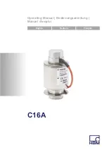
C16A

Summary of Contents for C16A C3

Page 1: ...Operating Manual Bedienungsanleitung Manuel d emploi English Deutsch Fran ais C16A...

Page 2: ...product descriptions are for general information only They are not to be understood as a guarantee of quality or durability nderungen vorbehalten Alle Angaben beschreiben unsere Produkte in allgemein...

Page 3: ...Operating Manual Bedienungsanleitung Manuel d emploi English Deutsch Fran ais C16A...

Page 4: ...onditions on site 12 6 Mechanical installation 13 6 1 Important precautions during installation 13 6 2 Preparation for installation 14 6 3 Assembly sequence 15 6 4 Procedure for special installation s...

Page 5: ...3 Options for C16A 32 11 Dimensions 33 11 1 Dimensions and mounting parts for maximum capacity 20t to 60t 33 11 2 Dimensions and mounting parts for maximum capacity 100t to 400t 36 11 3 Dimensions of...

Page 6: ...only be operated by qualified personnel and as described in the Operating Manual It is also essential to comply with the legal and safety requirements for the application con cerned during use The sa...

Page 7: ...sducer is maintenance free S In accordance with national and local environmental protection and material recovery and recycling regula tions old transducers that can no longer be used must be disposed...

Page 8: ...e operation of the equipment and technologies described in this docu mentation S As commissioning engineers or service engineers they have successfully completed the training to qual ify them to repai...

Page 9: ...ine protection The transducers function passively and cannot implement any safety relevant cutoffs In the event of a fault the relevant precautions must estab lish safe operating conditions General da...

Page 10: ...nts and damage to property Symbol Significance WARNING This marking warns of a potentially dangerous situ ation in which failure to comply with safety require ments can result in death or serious phys...

Page 11: ...hrust piece mounting accessories to be ordered separately Maximum capacities 20 t 0 60 t Built in variant 1 S C16 ZOU44A Thrust pieces stainless for top and bottom 1 set 2 pieces can be used with C16...

Page 12: ...entric discs Maximum capacities 400 t S EPO3 400t Thrust piece for top incl clamping ring S C16 EPU109 Thrust piece for bottom incl 3 eccentric discs 3 2 Ground cable mounting accessories to be ordere...

Page 13: ...load cells or load application elements may be damaged The simplest and most usual solution here is to set up appropriate stops on the super structure scale platform that must be carefully set within...

Page 14: ...e steam cleaner as per DIN EN60529 Protection against corrosion The transducer must be protected against chemicals that could attack the transducer body steel or the cable Notice Acids and all substan...

Page 15: ...vides the highly flexible EEK ground cable which can be screwed on above and below the transducer S Make sure that the transducer cannot be overloaded S The optional outer braided wire cable covering...

Page 16: ...the transducer cannot be overloaded including while it is be ing mounted 6 2 Preparation for installation If you are using the thrust pieces EPO3 C16 EPU or C16 ZOU44A you must carry out the preparati...

Page 17: ...above the top thrust piece must be as smooth and level as possible The thrust pieces can be positioned or screwed directly onto concrete if the sur face quality is appropriate so that no further panel...

Page 18: ...acing upwards see Chapter 6 2 Orientate the bottom thrust piece so that the dowel pin faces in the direction that the cable output and type plate should also face Do not as yet permanently fix the bot...

Page 19: ...the loading point of the top thrust piece so that the load cells are just not under load and can still be aligned vertically Important The load cells must be aligned vertically otherwise restoring can...

Page 20: ...ocedure for special installation situations If the load cell support spacings are very wide or the plat form weighing machines have a high deflection it may be possible that measurement deviations occ...

Page 21: ...ad cells in inclined position Alternatively you can insert thin metal shims approx 0 5 mm thick under the thrust pieces at the points indic ated in Fig 6 4 Shims Fig 6 4 Inserting shims You can counte...

Page 22: ...ted rotation stop can be used when using the HBM mounting parts EPO3 C16 EPU or C16 ZOU44A as described in Chapter 6 2 on Page 14 If you wish to build and use mounting parts yourself HBM will provide...

Page 23: ...pplied in the standard version in a six wire configuration with open cable ends Notice Lay the cables so that no wear points can occur due to the natural motion of the transducer and so that no dam ag...

Page 24: ...7 1 Connection in six wire configuration white black gray Excitation voltage green red Shielding drain wire connected to housing Excitation voltage Sense lead Measurement signal blue Sense lead Measu...

Page 25: ...nal boxes or the VKK2R 8 Ex version for potentially explosive areas are available in the HBM product line for this purpose The output signal is then the average of the individual output signals Import...

Page 26: ...be planned locally by an appropriate specialist The load cells with shielded round cables are EMC tested in accordance with EC directives and identified by CE certification Points to be observed S Us...

Page 27: ...m You must therefore lay sufficiently dimensioned po tential equalization lines to compensate for possible potential differences Important Potential equalization is specified for applications in po te...

Page 28: ...disposal regulations may differ from country to country we ask that you contact your supplier to determ ine what type of disposal or recycling is legally applicable in your country Packaging The orig...

Page 29: ...l vmin of Emax 0 0200 0 0068 NTEP III LM 2 Minimum load cell verification interval of scale as per EN45501 emin kg Temperature coeffi cient of zero signal per 10K TC0 of Cn 0 0285 Nominal rated sens i...

Page 30: ...mperat ure range Btu 30 70 Storage temperature range Btl 50 85 Limit load EL of Emax 150 Breaking load Ed 350 200 300 Relative perm oscil latory stress oscilla tion width as per DIN 50100 Fsrel 70 Nom...

Page 31: ...ecause of the off center load compensation the sensitivity and output resistance are matched in such a way that when there is eccentric loading the scale display is within the permissible error limits...

Page 32: ...f load cells emin kg 5 6 10 10 10 10 10 6 20 10 10 4 20 10 50 8 Temperature coefficient of zero signal per 10K TC0 of Cn 0 0140 0 0116 0 0234 Nominal rated sensitivity Cn mV V 2 Sensitivity tolerance...

Page 33: ...0 h IP69 K water at high pressure steam cleaner 4 Material Measuring body housing Stainless steel 5 Cable entry Stainless steel 5 Seal VitonR Cable sheath Thermoplastic elastomer 1 As per OIML R60 wit...

Page 34: ...s 32 A1460 4 0 HBM public C16A 10 3 Options for C16A S Accuracy classes C4 and C5 OIML on request S Cable length 20 m Emax 20 t 30 t S Cable length 40 m Emax 20 t 400 t S 20 m cable with metal mesh Em...

Page 35: ...in variant 1 C16 60 t and C16 ZOU44A max load per load cell 40 t 2 x M8 11 85 64 44 76 1 Fastening bolts shown rotated by 90 Dimensions in mm 1 mm 0 03937 inches C16 ZOU44A Cable length standard 20 t...

Page 36: ...C16 EPU44A a S 120 120 3 x M16 View from above 89 76 1 120 147 4 x M16 18 Dimensions in mm 1 mm 0 03937 inches EPO3 50 t C16 EPU44A Cable length standard 20 t 30 t 12 m 40 t 60 t 20 m Dowel pin 10 x...

Page 37: ...13 12 2 0 94 60 t 260 210 157 220 3 11 5 7 0 52 Built in variant 2 Emax C16 Thrust pieces A B C R ball amax 2 smax 3 FR 4 top bot tom at Smax at S 1 mm 20 t EPO3 50 t C16 EPU 44A 229 150 123 130 5 13...

Page 38: ...ting parts for maximum capacity 100t to 400t 120 120 K A M10 F E D G B I C H 4x M EPO EEK6 Ball R Dowel pin not included among the items supplied Cable length Standard 20 m 3x M16 EPU O ring only with...

Page 39: ...16 EPU109 412 1 5 260 205 240 196 160 26 109 Max capa city Thrust pieces top bottom 1 set 2 pieces jI jK R amax 1 smax 2 FR 3 at smax at s 1 mm 100 t EPO3 100 t C16 EPU64 106 165 290 4 18 8 6 0 48 200...

Page 40: ...c tion class pressure proof encapsulation d only differ in the area of the cable terminal box compared to standard load cells All other dimensions can be found in the data sheets of the standard load...

Page 41: ...Operating Manual Bedienungsanleitung Manuel d emploi English Deutsch Fran ais C16A...

Page 42: ...ziehen 11 4 Funktionsweise 12 5 Bedingungen am Einbauort 13 6 Mechanischer Einbau 14 6 1 Wichtige Vorkehrungen beim Einbau 14 6 2 Vorbereitung der Montage 15 6 3 Montageablauf 17 6 4 Vorgehensweise be...

Page 43: ...10 3 Optionen f r C16A 35 11 Abmessungen 36 11 1 Abmessungen und Einbauteile f r Nennlasten 20 t bis 60 t 36 11 2 Abmessungen und Einbauteile f r Nennlasten 100 t bis 400 t 39 11 3 Abmessungen der W g...

Page 44: ...der Aufnehmer nur von qualifiziertem Personal und nach den Angaben in der Bedienungsanleitung betrieben werden Bei der Verwendung sind zus tzlich die f r den jeweiligen Anwendungsfall erforderlichen R...

Page 45: ...e ausdr ckliche Zu stimmung weder konstruktiv noch sicherheitstech nisch ver ndert werden S Der Aufnehmer ist wartungsfrei S Nicht mehr gebrauchsf hige Aufnehmer sind gem den nationalen und rtlichen V...

Page 46: ...ess oder Automatisie rungsanlagen und sind im Umgang mit den Anlagen unterwiesen Sie sind mit der Bedienung der in dieser Dokumentation beschriebenen Ger te und Technolo gien vertraut S Sie sind Inbet...

Page 47: ...er cksichtigt so dass Restgefahren minimiert werden Insbesonders betrifft dies den Personen und Anlagenschutz Die Aufnehmer arbeiten passiv und k nnen keine sicherheitsrelevanten Abschaltungen vor neh...

Page 48: ...e Hinweise f r Ihre Sicherheit sind besonders ge kennzeichnet Beachten Sie diese Hinweise unbedingt um Unf lle und Sachsch den zu vermeiden Symbol Bedeutung WARNUNG Diese Kennzeichnung weist auf eine...

Page 49: ...ung Symbol Tipp Diese Kennzeichnung weist auf Anwendungstipps oder andere f r Sie n tzliche Informationen hin Hervorhebung Siehe Kursive Schrift kennzeichnet Hervorhebungen im Text und kennzeichnet Ve...

Page 50: ...g 3 1 Einbauzubeh r Druckst cke zus tzlich zu beziehen Nennlasten 20 t 0 60 t Einbauvariante 1 S C16 ZOU44A Druckst cke rostfrei f r oben und unten 1 Satz 2 St ck verwendbar mit C16 60 t bis zu einer...

Page 51: ...klusive 3 Exzenterscheiben Nennlasten 400 t S EPO3 400t Druckst ck f r oben inklusive Spannring S C16 EPU109 Druckst ck f r unten inklusive 3 Exzenterscheiben 3 2 Einbauzubeh r Erdungskabel zus tzlich...

Page 52: ...zu Besch digungen an den W gezellen oder den Lasteinleitungen kommen kann Die einfachste und g n gigste L sung sind hier entsprechende Anschl ge an der Aufbaukonstruktion Waagenplattform die sorgf lt...

Page 53: ...llten die Auf nehmer gegen dauerhafte Feuchteeinwirkung gesch tzt werden Korrosionsschutz Der Aufnehmer muss gegen Chemikalien gesch tzt werden die den Stahl des Aufnehmerk rpers oder das Kabel angrei...

Page 54: ...erhalb des Aufnehmers ange schraubt wird S Stellen Sie sicher dass der Aufnehmer nicht berlastet werden kann S Das optional mit einem u eren Metallgeflecht ber zogene Kabel bei einigen C16A z B mit de...

Page 55: ...habung St e oder St rze k nnen zu permanenten Sch den am Auf nehmer f hren Sorgen Sie daf r dass auch bei der Montage keine berlastung des Aufnehmers auftreten kann 6 2 Vorbereitung der Montage Falls...

Page 56: ...Anordnung des Spannstiftes zur Verdrehsicherung Durch die Tiefe der Bohrung ergibt sich der korrekte Sitz des Stiftes Die Stellfl chen bzw Fundamente unter dem unteren Druckst ck Lastausleitung und be...

Page 57: ...steinleitungsteile mit Spannstift zur Verdrehsicherung unten und die ohne Spannstift oben siehe Kapitel 6 2 Richten Sie das untere Druckst ck so aus dass der Spannstift in die Richtung zeigt in die sp...

Page 58: ...tere Abdichtung der Abdichtstulpe um das untere Druckst ck Setzen Sie die W gezellen in das untere Druckst ck mit kreisender Bewegung so ein dass der Spannstift am Druckst ck in die Aussparung der Ve...

Page 59: ...te wie eben an der anderen Stirnseite vor Kontrollieren Sie nach dem gesamten Einbau nochmals bei frei schwingender Br cke die lotrechte Einbaulage aller W gezellen Falls Korrekturen notwendig sind f...

Page 60: ...brollbewegung durch seitliches Auswandern der oberen Lasteinleitungspunkte der W gezellen unter Last wenn die Kontaktzone zwischen Druckst ck und W gezelle weit unterhalb der biegeneutralen Faser der...

Page 61: ...esem Effekt dadurch begegnen dass Sie die Auflagerpunkte an der W ge br cke soweit wie m glich nach oben in Richtung der biegeneutralen Faser verlegen Hinweis Stellen Sie vor dem ersten Belasten Befah...

Page 62: ...ergestellte Ein bauteile verwenden m chten stellt Ihnen HBM Zeichnun gen bereit die Lage und Montage der Verdrehsicherung zeigen Achten Sie jedoch darauf dass die angegebenen Toleranzen f r die Lage d...

Page 63: ...mit offenem Kabelende ausgeliefert Hinweis Verlegen Sie das Kabel so dass bei Eigenbewegungen des Aufnehmers keine Scheuerstellen entstehen und damit eine Besch digung des Kabelmantels auftreten kann...

Page 64: ...ensionierten berspannungsschutz 7 1 Anschluss in Sechsleiter Technik wei schwarz grau Speisespannung gr n rot Schirm Beilauflitze an Geh use Speisespannung F hlerleitung Messsignal blau F hlerleitung...

Page 65: ...zellen anschlusskabel miteinander verbinden Daf r stehen die Klemmenk sten des Typs VKK oder im Ex Bereich die Version VKK2R 8 Ex aus dem HBM Programm zur Ver f gung Das Ausgangssignal ist dann der Mi...

Page 66: ...m glichkeiten und der unterschiedlichen Randbedingungen vor Ort k nnen wir Ihnen nur Hinweise f r einen sachgerechten Anschluss geben Das f r Ihre Anwendung passende Schirmungs konzept muss vor Ort vo...

Page 67: ...n HBM an Schlie en Sie von dort aus das Messkabel zur Elektronik sowohl fl chig am Klemmenkasten als auch fl chig am schirmenden Geh use der Elektronik an S Der Schirm der Anschlusskabel darf nicht al...

Page 68: ...16A 8 Wartung und Reinigung Der Aufnehmer ist wartungsfrei Der Aufnehmer darf auch mit einem Dampfstrahler gereinigt werden Beachten Sie jedoch dabei die in EN 60 529 unter Schutzart IP69K genannten B...

Page 69: ...itten wir Sie im Bedarfsfall Ihren Liefe ranten anzusprechen welche Art von Entsorgung oder Recycling in Ihrem Land vorgeschrieben ist Verpackungen Die Originalverpackung von HBM besteht aus recycle b...

Page 70: ...ezelle vmin v Emax 0 0200 0 0068 NTEP III LM 2 Mindestteilungswert der Waage nach EN 45 501 emin kg Temperaturkoeffizient des Nullsignals pro 10 K TK0 v Cn 0 0285 Nennkennwert Cn mV V 2 Kennwerttolera...

Page 71: ...stempera turbereich Btu 30 70 Lagerungstemperatur bereich Btl 50 85 Grenzlast EL v Emax 150 Bruchlast Ed 350 200 300 Relative zul Schwing beanspruchung Schwingbreite nach DIN 50 100 Fsrel 70 Nennmessw...

Page 72: ...3 Durch Eckenlastvorabgleich sind Kennwert und Ausgangswiderstand so aufeinander abgestimmt dass bei au ermittiger Belastung die Anzeige der Waage innerhalb der zul ssigen Fehlergrenzen liegt 4 Die We...

Page 73: ...llen emin kg 5 6 10 10 10 10 10 6 20 10 10 4 20 10 50 8 Temperaturkoeffizient des Nullsignals pro 10 K TK0 v Cn 0 0140 0 0116 0 0234 Nennkennwert Cn mV V 2 Kennwerttoleranz2 0 5 Temperaturkoeffizient...

Page 74: ...ruck Dampf strahlreinigung 4 Material Messk rper Geh use nichtrostender Stahl5 Kabeleinf hrung nichtrostender Stahl5 Dichtung VitonR Kabelmantel thermoplastisches Elastomer 1 Nach OIML R60 mit PLC 0 7...

Page 75: ...C16A A1460 4 0 HBM public 35 10 3 Optionen f r C16A S Genauigkeitsklassen C4 und C5 OIML auf Anfrage S Kabell nge 20 m Emax 20 t 30 t S Kabell nge 40 m Emax 20 t 400 t S 20 m Kabel mit Metallgeflecht...

Page 76: ...riante1 C16 60 t und C16 ZOU44A max Belastung je W gezelle 40 t 2 x M8 11 85 64 44 76 1 Befestigungsschraube um 90 gedreht gezeichnet Abmessungen in mm C16 ZOU44A Kabell nge Standard 20 t 30 t 12 m 40...

Page 77: ...nd C16 EPU44A a S 120 120 3 x M16 Ansicht von oben 89 76 1 120 147 4 x M16 18 Abmessungen in mm EPO3 50 t C16 EPU44A Kabell nge Standard 20 t 30 t 12 m 40 t 60 t 20 m Spannstift 10 x 30 Ver drehsicher...

Page 78: ...2 0 94 60 t 260 210 157 220 3 11 5 7 0 52 Einbauvariante 2 Emax C16 Druckst cke A B C R Kugel amax 2 Smax 3 FR 4 oben unten bei Smax bei S 1 mm 20 t EPO3 50 t C16 EPU 44A 229 150 123 130 5 13 6 4 0 4...

Page 79: ...n und Einbauteile f r Nennlasten 100 t bis 400 t 120 120 K A M10 F E D G B I C H 4x M EPO EEK6 Kugel R Spannstift im Liefer umfang enthalten Kabell nge Standard 20 m 3x M16 EPU O Ring nur bei EPU64 S...

Page 80: ...9 412 1 5 260 205 240 196 160 26 109 Nenn last Druckst cke oben unten 1 Satz 2 St ck jI jK R amax 1 smax 2 FR 3 bei smax bei s 1 mm 100 t EPO3 100 t C16 EPU64 106 165 290 4 18 8 6 0 48 200 t 400 2 9 7...

Page 81: ...zart Druckfeste Kapselung d unterscheiden sich von denen der Standard W gezellen lediglich im Bereich des Kabel anschlusskastens Entnehmen Sie bitte alle anderen Ab messungen den Datenbl ttern der Sta...

Page 82: ...Abmessungen 42 A1460 4 0 HBM public C16A...

Page 83: ...Operating Manual Bedienungsanleitung Manuel d emploi English Deutsch Fran ais C16A...

Page 84: ...rre comme accessoire de montage commander s par ment 11 4 Principe de fonctionnement 12 5 Conditions environnantes respecter 13 6 Montage m canique 14 6 1 Pr cautions importantes lors du montage 14 6...

Page 85: ...ment 29 10 Caract ristiques techniques 30 10 1 C16A D1 30 10 2 C16A C3 33 10 3 Options pour C16A 35 11 Dimensions 36 11 1 Dimensions et pi ces de montage pour charges nominales de 20 t 60 t 36 11 2 Di...

Page 86: ...ci doit uniquement tre utilis par du personnel qualifi conform ment aux instructions du manuel d emploi De plus il convient pour chaque cas particulier de respecter les r glements et consignes de s c...

Page 87: ...ue car l ac cent est mis sur la sensibilit lev e S Il est interdit de modifier le capteur sur le plan concep tuel ou celui de la s curit sans accord explicite de notre part S Le capteur est sans entre...

Page 88: ...ure et d automatisation et les ma trisent en tant que charg s de projet S Elles sont op rateurs des installations de mesure ou d automatisation et ont t form es pour pouvoir utili ser les installation...

Page 89: ...s curit de la technique de mesure et d automatisation doivent tre r alis es de fa on minimiser les dangers r siduels Cela concerne notamment la protection des personnes et des instal lations Les capt...

Page 90: ...s curit sont rep r es d une mani re particuli re Respectez imp rati vement ces consignes pour viter tout accident et ou dommage mat riel Symbole Signification AVERTISSEMENT Ce marquage signale un ris...

Page 91: ...mbole Conseil Ce marquage est associ des conseils d utilisation ou autres informations utiles Mise en valeur Voir Les caract res en italique mettent le texte en valeur et signalent des renvois des cha...

Page 92: ...chet de graisse S Notice de montage 3 1 Pi ces d appui comme accessoires de montage commander s par ment Charges nominales 20 t 0 60 t Variante de montage 1 S C16 ZOU44A Pi ces d appui inoxydables pou...

Page 93: ...i ce d appui pour le bas avec 3 disques d excentrique Charges nominales 400 t S EPO3 400t Pi ce d appui pour le haut avec bague de serrage S C16 EPU109 Pi ce d appui pour le bas avec 3 disques d excen...

Page 94: ...ine d endommager les pesons ou les l ments de mise en charge La solution la plus simple et la plus courante consiste installer des but es appropri es sur la construction plateforme qui doivent alors t...

Page 95: ...toutefois tre prot g s contre une pr sence permanente d humidit Protection contre la corrosion Le capteur doit tre prot g contre les produits chi miques susceptibles d attaquer l acier du corps du cap...

Page 96: ...uple EEK viss au dessus et au dessous du capteur S S assurer que le capteur ne peut pas tre surcharg S Le c ble avec tresse m tallique ext rieure disponible en option pour certains C16A par ex r f ren...

Page 97: ...gement irr versible du capteur Veiller ce que le capteur ne puisse pas tre surcharg lors du montage galement 6 2 Pr paration du montage En cas d utilisation des pi ces d appui EPO3 C16 EPU ou C16 ZOU4...

Page 98: ...de la goupille Les surfaces au sol ou les fondations sous la pi ce d ap pui inf rieure transfert de charge et les surfaces au dessus de la pi ce d appui sup rieure doivent tre aussi planes et horizon...

Page 99: ...e anti rotation en bas et les l ments sans goupille en haut voir chapitre 6 2 Orienter la pi ce d appui inf rieure de fa on ce que la goupille pointe dans la direction o sera plus tard la sortie de c...

Page 100: ...en vue de l tanch it future de la manchette d tanch it Ins rer les pesons dans la pi ce d appui inf rieure dans un mouvement circulaire de fa on ce que la goupille sur la pi ce d appui s ins re dans l...

Page 101: ...pour l autre face Une fois le montage termin contr ler une nouvelle fois l aplomb de tous les pesons lorsque le pont bouge librement Si des corrections s av rent n cessaires les effectuer avec le pon...

Page 102: ...ar le d placement lat ral sous charge des points d ap plication de charge sup rieurs des pesons lorsque la zone de contact entre la pi ce d appui et le peson se trouve bien en dessous de la fibre flex...

Page 103: ...ruction sp ciale dans laquelle les points d appui sur le pont bascule sont remont s aussi haut que possible en direction de la fibre flexion neutre Note Avant de charger le pont pour la premi re fois...

Page 104: ...des pi ces de montage fabriqu es par ses soins HBM met des dessins disposition qui montrent l empla cement et le montage de la s curit anti rotation Veiller cependant ce que les tol rances indiqu es p...

Page 105: ...ont livr s en technique six fils avec extr mit de c ble nue Note Poser le c ble de fa on ce qu il n y ait pas de zones de frottement en cas de mouvements du capteur qui pourraient endommager la gaine...

Page 106: ...5 Protection CEM 7 1 Raccordement en technique six fils blanc noir gris Tension d alimentation vert rouge Blindage fil de rep re sur le bo tier Tension d alimentation Fil de contre r action Signal de...

Page 107: ...rdement des pesons HBM propose cet effet les bo tiers de raccordement VKK ou en zone Ex la version VKK2R 8 Ex Le signal de sortie correspond alors la valeur moyenne des diff rents sig naux de sortie I...

Page 108: ...ion et de conditions sur site nous pouvons uniquement vous don ner des indications pour un raccordement correct Le concept de blindage adapt votre application doit tre planifi sur place par un sp cial...

Page 109: ...rder le c ble de mesure menant l lectronique aussi bien en nappe au niveau du bo tier de rac cordement qu en nappe au niveau du bo tier blind de l lectronique S Le blindage du c ble de liaison ne doit...

Page 110: ...et nettoyage Le capteur est sans entretien Le capteur peut galement tre nettoy avec un net toyeur jet de vapeur Il convient toutefois de respecter les conditions mentionn es dans la norme EN 60 529 po...

Page 111: ...uctions d limination des d chets dif f rent d un pays l autre nous vous prions le cas ch ant de demander votre fournisseur quel type d li mination des d chets ou de recyclage est mis en uvre dans votr...

Page 112: ...de Emax 0 0200 0 0068 NTEP III LM 2 Valeur minimale d un chelon de l instrument de pe sage selon EN 45 501 emin kg Coefficient de temp rature du signal z ro par 10 K TK0 de Cn 0 0285 Sensibilit nomina...

Page 113: ...tile de temp rature Btu 30 70 Plage de temp rature de stockage Btl 50 85 Charge limite EL de Emax 150 Charge de rupture Ed 350 200 300 Charge dynamique admissible amplitude vibratoire selon DIN 50 100...

Page 114: ...arges d angle la sensibilit et la r sistance de sortie sont adapt es l une l autre de sorte que l affichage de l instrument de pesage se trouve dans les limites d erreur admissibles en cas de charge e...

Page 115: ...axi de pesons emin kg 5 6 10 10 10 10 10 6 20 10 10 4 20 10 50 8 Coefficient de temp rature du signal z ro par 10 K TK0 de Cn 0 0140 0 0116 0 0234 Sensibilit nominale Cn mV V 2 Tol rance de sensibilit...

Page 116: ...au jet de vapeur 4 Mat riau l ment de mesure bo tier Acier inoxydable5 Entr e de c ble Acier inoxydable5 Garniture d tanch it VitonR Gaine de c ble lastom re thermoplastique 1 Selon OIML R60 avec PLC...

Page 117: ...A1460 4 0 HBM public 35 10 3 Options pour C16A S Classes de pr cision C4 et C5 OIML sur demande S Longueur de c ble 20 m Emax 20 t 30 t S Longueur de c ble 40 m Emax 20 t 400 t S C ble de 20 m avec t...

Page 118: ...iante de montage 1 C16 60 t et C16 ZOU44A charge maxi par peson 40 t 2 x M8 11 85 64 44 76 1 Vis de fixation repr sent e tourn e 90 Dimensions en mm C16 ZOU44A Longueur de c ble standard 20 t 30 t 12...

Page 119: ...et C16 EPU44A a S 120 120 3 x M16 Vue de dessus 89 76 1 120 147 4 x M16 18 Dimensions en mm EPO3 50 t C16 EPU44A Longueur de c ble standard 20 t 30 t 12 m 40 t 60 t 20 m Goupille de serrage 10 x 30 s...

Page 120: ...2 0 94 60 t 260 210 157 220 3 11 5 7 0 52 Variante de montage 2 Emax C16 Pi ces d appui A B C R sph re amax 2 Smax 3 FR 4 sup inf pour Smax pour S 1 mm 20 t EPO3 50 t C16 EPU 44A 229 150 123 130 5 13...

Page 121: ...de montage pour charges nom de 100 t 400 t 120 120 K A M10 F E D G B I C H 4x M EPO EEK6 Sph re R Goupille comprise dans la livraison Longueur de c ble standard 20 m 3x M16 EPU Joint torique uniq pou...

Page 122: ...12 1 5 260 205 240 196 160 26 109 Charge nom Pi ces d appui sup inf 1 jeu 2 unit s jI jK R amax 1 smax 2 FR 3 pour smax Pour s 1 mm 100 t EPO3 100 t C16 EPU64 106 165 290 4 18 8 6 0 48 200 t 400 2 9 7...

Page 123: ...otection d encapsulage antid flagrant d et celles des pesons standards r side dans le bo tier de raccordement de c ble Pour toutes les autres dimen sions se reporter aux caract ristiques techniques de...

Page 124: ...www hbm com HBM Test and Measurement Tel 49 6151 803 0 Fax 49 6151 803 9100 info hbm com measure and predict with confidence A1460 4 0 7 2002 5000 HBM public...

Reviews: