Hayter Powertrim 407F Owner'S Handbook Manual Download Page 28

Torque Specification Chart

FOR STANDARD MACHINE HARDWARE (Tolerance  ± 20%)

Hardware
Grade

SAE Grade 2

SAE Grade 5

SAE Grade 8

Size Of

in/lbs

in/lbs

in/lbs

Hardware

ft/lbs

Nm.

ft/lbs

Nm.

ft/lbs

Nm.

8-32

19

2.1

30

3.4

41

4.6

8-36

20

2.3

31

3.5

43

4.9

10-24

27

3.1

43

4.9

60

6.8

10-32

31

3.5

49

5.5

68

7.7

1/4-20

66

7.6

8

10.9

12

16.3

1/4-28

76

8.6

10

13.6

14

19.0

5/16-18

11

15.0

17

23.1

25

34.0

5/16-24

12

16.3

19

25.8

27

34.0

3/8-16

20

27.2

30

40.8

45

61.2

3/8-24

23

31.3

35

47.6

50

68.0

7/16-14

30

40.8

50

68.0

70

95.2

7/16-20

35

47.6

55

74.8

80

108.8

1/2-13

50

68.0

75

102.0

110

149.6

1/2-20

55

74.8

90

122.4

120

163.2

9/16-12

65

88.4

110

149.6

150

204.0

9/16-18

75

102.0

120

163.2

170

231.2

5/8-11

90

122.4

150

204.0

220

299.2

5/8-18

100

136

180

244.8

240

326.4

3/4-10

160

217.6

260

353.6

386

525.0

3/4-16

180

244.8

300

408.0

420

571.2

7/8-9

140

190.4

400

544.0

600

816.0

7/8-14

155

210.8

440

598.4

660

897.6

1-8

220

299.2

580

788.8

900

1,244.0

1-12

240

326.4

640

870.4

1,000

1,360.0

Hex Head Capscrew

Hex Nut

Lockwasher

Washer

Carriage Bolt

NOTES

1. These torque values are to be used for all hardware

excluding: locknuts, self-tapping screws, thread forming
screws, sheet metal screws and socket head setscrews.

2. Recommended seating torque values for locknuts:

a. for prevailing torque locknuts - use 65% of grade 5

torques.

b. for flange whizlock nuts and screws - use 135% of

grade 5 torques.

3. Unless otherwise noted on assembly drawings, all torque

values must meet this specification.

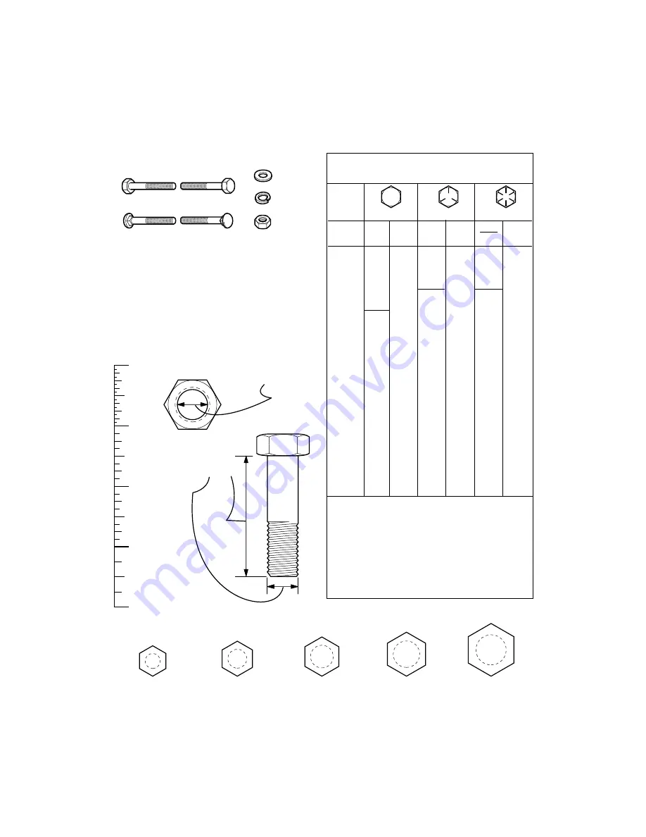
Hardware Identification  &  Torque Specifications

Common Hardware Types

Screw, 1/2 x 2

Body

Diameter

Body

Length

Inside
Diameter

Nut, 1/2”

No

Marks

3/8” Bolt or Nut

Wrench—9/16”

3/8

5/16” Bolt or Nut

Wrench—1/2”

5/16

1/4” Bolt or Nut

Wrench—7/16”

1/4

1/2” Bolt or Nut

Wrench—3/4”

1/2

DIA.

7/16
DIA.

7/16” Bolt or Nut

Wrench (Bolt)—5/8”

Wrench (Nut)—11/16”

Wrench & Fastener Size Guide

Standard Hardware Sizing

When a washer or nut is identified as 

1/2”

, this is the

Nominal size, meaning the inside diameter is 1/2 inch; if a
second number is present it represent the 

threads per inch

When bolt or capscrew is identified as 

1/2 - 16 x 2”

, this

means the 

Nominal size, or body diameter is 1/2 inch; the

second number represents the 

threads per inch (16 in this

example, and the final number is the 

body length of the

bolt or screw (in this example 2 inches long).

The guides and ruler furnished below are designed to
help you select the appropriate hardware and tools.

0

1/4

3/4

1/2

1

1/4

3/4

1/2

2

1/4

3/4

1/2

3

1/4

3/4

1/2

4

P

PTS - 6

Summary of Contents for Powertrim 407F

Page 1: ...POWERTRIM Code 407F OWNER S HANDBOOK P O N L A I R E S E D O C ART NO 111 3445 Rev A 407F 310000001 Issue 10 2009...

Page 2: ...2 1739579 TABLE OF CONTENTS LIMITED WARRANTY OPERATOR SAFETY ASSEMBLY OPERATION MAINTENANCE TROUBLESHOOTING SPECIFICATIONS REPAIR PARTS 3 4 8 11 14 19 21 23...

Page 3: ...lade brake units and other such devices are not applicable Only machines fitted with a genuine Hayter friction disc which are used in accordance with the recommended operating and maintenance procedur...

Page 4: ...t Also wear long trousers Do not wear shorts 8 Do not wear loose clothing or jewelry They can be caught in moving parts 9 Always wear safety goggles or safety glasses with side shields when operating...

Page 5: ...hanging direction on slopes Do remove objects such as rocks tree limbs etc Do watch for holes ruts or bumps Tall grass can hide obstacles Do not trim near drop offs ditches or em bankments The operato...

Page 6: ...to do so in this Manual Service and repair proce dures can be done with the machine in an upright position Some procedures will be easier if the machine is lifted on a raised platform or working surf...

Page 7: ...al Before Operating This Machine 3 WARNING Thrown Objects Keep Bystanders Away Read User Instructions Before Operating This Machine 4 Do Not Trim Up And Down Slopes Trim Across Slopes 5 WARNING Rotati...

Page 8: ...sembled and positioned in the carton for ship ment References to the right or left hand side of the machine are from the viewpoint of the opera tor s position behind the unit REMOVE THE TRIMMER FROM C...

Page 9: ...cables are not caught between the upper and lower handle 4 Tighten the handle ad justment knobs Make sure the handle pivots are locked in place NOTE The handlebar height is adjustable See How To Adju...

Page 10: ...ith Oil 1 Remove the oil fill cap dipstick shown in Figure 4 Fill the crankcase to the FULL line on oil fill cap dipstick DO NOT OVER FILL 2 Install the oil fill cap dipstick and tighten securely Fill...

Page 11: ...the trimmer head Throttle Control Lever Controls the speed or stops the engine Recoil Starter Handle The engine is equipped with an easy pull recoil starter EYE PROTECTION WARNING Debris thrown from t...

Page 12: ...n the FAST position to run the engine at full speed 2 Pull the throttle control lever back to de crease engine speed Push the throttle control lever forward to increase engine speed 3 To stop the engi...

Page 13: ...noxide an odorless and deadly gas Keep hands feet hair and loose clothing away from the machine and any moving parts on the engine Avoid the muffler and surround ing areas Temperatures may ex ceed 150...

Page 14: ...Lines 1 Check Trimmer Head Engagement Engine Machine Cleaning 2 Check Nuts and Bolts Check Spark Plug Change Engine Oil Service Air Filter 3 Lubricate Jackshaft Assembly Lubricate Wheel Bearings Note...

Page 15: ...the engine is warm For the proper oil capacity see the en gine manufacturer s instructions 1 Disconnect spark plug wire from the spark plug 2 Remove the oil drain plug as shown in Figure 11 3 Drain a...

Page 16: ...g 3 Before installing the spark plug coat the threads lightly with oil for easy removal Tighten the spark plug to a torque of 15 foot pounds Figure 12 Spark Plug Feeler Gauge 0 030 ADJUST THE HEIGHT O...

Page 17: ...im mer line keep the trimmer line moist If not kept moist the nylon trimmer line will be come dry and brittle Keep extra trimmer line in a can of water The line will then stay flexible and easy to cha...

Page 18: ...immer Completely clean the machine Put the machine in a building that has good ventilation Engine To prevent engine damage when the ma chine is in storage for 30 days or more fol low the steps below L...

Page 19: ...ne Clean carburetor or fuel line Dirty air filter Replace air filter Carburetor out of adjustment See authorized dealer Engine flooded Wait several minutes before starting Throttle control lever in in...

Page 20: ...less than 1 2 this length replace the line Engine not set at FAST speed Move engine throttle lever to FAST position Trimmer vibrates Trimmer line lengths are substantially different Adjust trimmer li...

Page 21: ...rsepower values are derived at 3600 RPM Actual gross engine power will be lower and is affected by among other things ambient operating conditions and engine to engine variability Given both the wide...

Page 22: ...are available from your local Hayter authorised dealer the store where the mower was purchased or a service shop recommended by the store If you are unable to obtain parts or service in the manner ou...

Page 23: ...Repair Parts PTS 1...

Page 24: ...Handle And Wheels NOTE Unless noted otherwise use the standard hardware torque specification chart POWERTRIM Code 407F PTS 2...

Page 25: ...T Axle 17 MU015X84MA WASHER 18 MU0020X3MA SPACER 19 MU740190MA ASSEMBLY Axle Bracket 20 MU740188MA SCREW 21 MU26X274MA BOLT Carriage 22 MU711935MA DECK 23 MU740150E701MA BOLT 24 MU0025X6MA SHIELD Trai...

Page 26: ...Cutting Head And Shield NOTE Unless noted otherwise use the standard hardware torque specification chart POWERTRIM Code 407F PTS 4...

Page 27: ...1 MU740171MA SPACER 12 MU740173MA BELT 13 MU711933MA PULLEY Idler 14 MU740244MA PULLEY Engine 15 MU740179MA PULLEY Idler 16 MU740183MA LOCKWASHER 17 MU018X31MA BOLT 18 MU001X20MA SCREW 19 MU26X235MA G...

Page 28: ...crews thread forming screws sheet metal screws and socket head setscrews 2 Recommended seating torque values for locknuts a for prevailing torque locknuts use 65 of grade 5 torques b for flange whizlo...

Page 29: ......

Page 30: ......

Reviews: