background image

27

GB

Translation

The lift does not move unless the seat is in the correct travel 
position.

To put the lift into operation, proceed as follows:
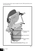
- bring down the arms 

W

 and 

U

 from the vertical position, as shown in fig . 4, to a 

horizontal position, as shown in fig . 5 .

- the same applies to the seat 

E

- by lifting the handle 

Y

, you can also tilt the foot rest 

T

 from a folded position fig . 

4 to a use position fig . 5; after that, you can get on the lift . Starting and moving the 
lift is made by moving the joystick 

Q

 fig . 5, as follows:

- to move to the right, move the joystick to the right and hold .
- to move to the left, move the joystick to the left and hold
- we do not recommend that you interrupt the command unless in case of obstacles
- to stop the lift at either end of the track, the control joystick must remain actuated 

until the lift reaches the charging contacts and stops on its own, followed by the blue 
LED 

I

 on the joystick arm lighting up, this indicating that the battery is charging 

from the power supply

- if the lift is stopped on the track outside the charging elements, it will beep to warn 

that the battery is not charging, and therefore that it must be moved so that the lift 
may reach the charging contacts

- when the travel ends and the top of the track is reached, the seat 

E

 with backrest 

and arms 

W

 and 

U

 fig . 5 are rotated to max . 90° to facilitate the user to get on and 

off the seat . The standard elevator has a fixed seat . Optionally it can be equipped 
with a manual rotation of the seat . Next are the steps for using this function:

- lift one of the handles 

{

 and slowly rotate the seat . After the seat starts to rotate 

release the handle 

{

 and continue the rotation in the direction you have to get 

of the lift . The rotation of the seat stops at 75º - fig no 5 .1 . if you want the seat to 
rotate to 90º, lift the handle 

{

 again and turn more in the same direction until the 

seat reaches 90º .

- to get back to the normal running position lift again the handle 

{

 and move in the 

opposite direction as described above until the seat reaches the normal running 
position .

Optionally, the stair lift can be equipped with electrical swivel seat function .
This movement is controlled by button 

R

 fig . 5, as follows:

- actuate the button in the right for right lifts or in the left for left lifts, and rotating 

will occur as long as the button is pressed down, automatically stopping at a max . 
angle of rotation of 90°

- to return the backrest and seat in normal travel position fig . 6, press the same button 

on the reverse side .

Summary of Contents for HW 10

Page 1: ...BEDIENUNGSANLEITUNG KURVENLIFT MODELL L 06 HW10 HW11 INSTRUCTIONS FOR USE STAIRLIFT MODEL L 06 HW10 HW11 INSTRUC IUNI DE UTILIZARE LIFT DE TREPTE MODEL L 06 HW10 HW11 D GB RO...

Page 2: ...ALE Seite 3 3 1 ALLGEMEINE BESCHREIBUNG 3 2 TECHNISCHE DATEN 3 3 EINFL SSE AUF DIE UMWELT 4 BEDIENUNG Seite 7 4 1 ALLGEMEINE HINWEISE 4 2 WICHTIGE HINWEISE VOR DER BENUTZUNG 4 3 SICHERHEITSVORSCHRIFTE...

Page 3: ...sowohl links als auch rechts an der Treppe installiert werden Er ist klappbar um so wenig Raum wie m glich im Parkbereich zu beanspruchen Eine sorgf ltige Planung und Ausf hrung des Treppenliftes erla...

Page 4: ...4 D bersetzung Abb 1 Oberes Rohr Unteres Rohr Zahnstange St tze Fu st tze...

Page 5: ...5 D bersetzung Sitz Antrieb Zahnstange Schiene Ausgleich Abb 2...

Page 6: ...hstlast 150 kg Betriebszeit der Batterien ohne Ladung betr gt ca 10 Fahrten bei einer Schienen l nge von 6 m und einer Steigung von 50 Auf Wunsch des Auftraggebers kann der Joystick in der rechten ode...

Page 7: ...EMEINE HINWEISE Der Ruf des Aufzuges vom zum Parkbereich erfolgt mittels Fernbedienung siehe Abb 3 durch anhaltendes Dr cken einer der beiden Pfeiltasten Halten Sie die Taste bedenkenlos gedr ckt denn...

Page 8: ...8 D bersetzung Um im Parkbereich Platz zu sparen ist der Lift zusammenklappbar siehe Abb 4 Abb 4 optional e ON OFF Schalter q Gr ne LED w NOT AUS Schalter Schl sselschalter...

Page 9: ...9 D bersetzung P Gurt O R ckenlehne Y Fu bretthebel T Fu brett Abb 5 W Rechte Armlehne E Sitzfl che R Drehsitzschalter U Linke Armlehne Q Steuer Joystick I Blaue LED...

Page 10: ...Ladestation gefahren werden muss Bei Fahrtende und wenn Sie das obere Schienenende erreicht haben k nnen Sie die Sitzfl che E sowie die R cken und Armlehnen W und U siehe Abb 5 bis max 90 drehen um I...

Page 11: ...11 D bersetzung Abb 5 1 Drehsitzhebel...

Page 12: ...nis Sensoren an der Fahreinheit sehen Sie in Abb 7 nach Fahrtende steigen Sie vom Lift ab und klappen diesen wie folgt zusammen Heben Sie die Sitzfl che E die Armlehnen W und U an und bet tigen Sie de...

Page 13: ...13 D bersetzung Abb 7...

Page 14: ...14 D bersetzung Die Angaben bez glich des Herstellungsdatums der Seriennummer und Angaben zum Herstellers k nnen dem Typenschild unter der Sitzfl che wie folgt entnommen werden...

Page 15: ...lle auf so dass der Lift nicht von Kindern oder unberechtigten Personen benutzt werden kann Pr fen Sie ob das Ladeger t eingesteckt ist Dies wird von der blauen LED angezeigt 4 3 SICHERHEITSVORSCHRIFT...

Page 16: ...Als Benutzer m ssen Sie lediglich Lift und Schienen sauber halten Es gelten folgende Empfehlungen nach ca 10 Benutzungen jedoch nicht l nger als 3 Tage ist die Schiene mit einem feuchten Lappen oder...

Page 17: ...e Verschlei teile deren Pr fung wir empfehlen sind alle F hrungs und St tzrollen das Antriebszahnrad sonstige Anhaltspunkte an welchen man sichtbare Verschlei spuren bemerkt 5 3 2 SICHERHEITSVORRICHTU...

Page 18: ...18 D bersetzung ANLAGE 1 ANGABEN ZUM PRODUKT Typ Serie Einkaufsdatum ANGABEN ZUM INSTALLATEUR Firma Ansprechpartner Sitz Telefon Fax E Mail ANGABEN ZUM K UFER Name Anschrift Telefon E Mail...

Page 19: ...R BUYERS pag 20 3 FEATURES pag 20 3 1 GENERAL DESCRIPTION 3 2 TECHNICAL DATA 3 3 ENVIRONMENTAL INFLUENCE 4 USE pag 24 4 1 ELEMENTS OF USE 4 2 PREVENTIVE MEASURES BEFORE USE 4 3 PROHIBITIONS 5 MAINTENA...

Page 20: ...r even three levels inside their home or building The elevator can be installed both on the inside and on the outside of the staircase to the left or right To occupy as little space in the parking are...

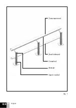
Page 21: ...21 GB Translation Fig 1 Upper tube Lower tube Rack Beam Sole support for pole...

Page 22: ...22 GB Translation Lift Rolling mechanism Drive pinion Rail Stabilization mechanism Fig 2...

Page 23: ...the batteries without them being loaded is of approx 10 trips for a rail length of 6 m at an angle of ascent of 50 The control joystick can be installed in the right arm or left arm 3 3 ENVIRONMENTAL...

Page 24: ...ecause the lift will slow down and stop automatically when it reaches the end of the track where you are We do not recommended that you press release the remote button when it reaches the end of the t...

Page 25: ...25 GB Translation To occupy less space the lift can be folded in the parking area as shown in fig no 4 Fig 4 Contact key optional e ON OFF button q Fault indication LED w STOP button...

Page 26: ...5 P Belt O Backrest Y Lifting descending arm for feet support T Feet support W Right arm E Seat R Chair spin command button left right U Left arm Q Command joystick movement lift up down I Battery ch...

Page 27: ...st be moved so that the lift may reach the charging contacts when the travel ends and the top of the track is reached the seat E with backrest and arms W and U fig 5 are rotated to max 90 to facilitat...

Page 28: ...28 GB Translation Fig 5 1 Swivel seat handle...

Page 29: ...s provided with obstacle sensors are shown in fig 7 after the travel has ended get off the lift and folds as follows lift the seat E arms W and U press the handle Y fig 5 then using the remote send th...

Page 30: ...30 GB Translation Fig 7...

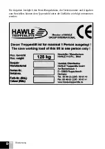
Page 31: ...31 GB Translation The information regarding the characteristics of the elevator the manufacturing date the manufacturing series and the manufacturer can be found on the labels provided under the seat...

Page 32: ...from being used by children or other unauthorized persons check that the battery charging source is not disconnected and that the battery LED shows the stair lift is charging 4 3 PROHIBITIONS traveli...

Page 33: ...user must do is to keep the lift and rail clean We recommend the following after cca 10 uses but no more than a 3 days clean the rail with a damp cloth and industrial alcohol or another non corrosive...

Page 34: ...y period we recommend an annual check of the lift by a company authorized by the manufacturer 5 3 MAINTENANCE LIST 5 3 1 WEAR PARTS Wear parts for which we recommend checking are all plastic guide and...

Page 35: ...35 GB Translation ANNEX 1 PRODUCT INFORMATION Type Series Date of purchase INSTALLER INFORMATION Company name Contact person Headquarters Phone Fax E mail BUYER INFORMATION Name Address Phone E mail...

Page 36: ...pag 37 3 CARACTERISTICI pag 37 3 1 DESCRIERE GENERALA 3 2 DATE TEHNICE 3 3 INFLUENTE ASUPRA MEDIULUI 4 UTILIZARE pag 41 4 1 ELEMENTE DE UTILIZARE 4 2 MASURI PREVENTIVE INAINTE DE UTILIZARE 4 3 INTERD...

Page 37: ...l doua sau chiar trei nivele in interiorul cladirilor Liftul poate fi instalat atat pe interiorul scarii cat si pe ex teriorul ei pe partea st ng sau pe partea dreapt Pentru a ocupa cat mai putin spat...

Page 38: ...38 RO Original Fig 1 eavasuperioar eav inferioar Cremalier Montant Suport cu talp...

Page 39: ...39 RO Original Lift Mecanism de rulare Pinion de antrenare Cale de rulare Mecanismdestabilizare Fig 2...

Page 40: ...rcare este de aproximativ 10 curse pentru o cale cu lungimea de 6 m la un unghi de urcare de 50 La cererea beneficiarului joystickul de comanda poate fi instalat in bratul dreapta sau in bratul stanga...

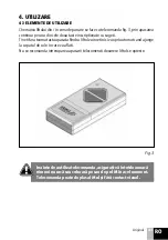
Page 41: ...ZARE 4 1 ELEMENTE DE UTILIZARE Chemarea liftului din in zona de parcare se face cu telecomanda fig 3 prin apasarea continua pe una din cele doua taste inscriptionate cu sageti Tineti fara teama tasta...

Page 42: ...RO Original n zona de parcare pentru a ocupa un spa iu c t mai mic liftul se poate plia a a cum este prezentat n fig 4 Fig 4 Cheie de contact optional e Buton ON OFF q Led semnalizare avarie w Buton S...

Page 43: ...P Centura O Spatar Y Maner ridicare coborare T Suport picioare W Brat dreapta E Sezut R Buton comanda rotire ezut stanga dreapta U Brat stanga Q Joystick comanda deplasare lift sus jos I Led semnaliza...

Page 44: ...s ajung pe contactele de nc rcare cand se termina deplasarea si se ajunge in partea superioara a caii de rulare sezutul E impreuna cu spatarul si bratele W si U fig 5 se roteste pana la max 900 pentru...

Page 45: ...45 RO Original Liftul nu se deplaseaz dec t dac ezutul se afl n pozi ie corect de mers Fig 5 1 Manet rotire ezut...

Page 46: ...e de pe lift prev zute cu senzori pentru obstacole sunt prezentate n fig 7 dupa incheierea deplasarii se coboara de pe lift si se pliaza astfel se ridica sezutul E bratele W si U se apasa manerul Y fi...

Page 47: ...47 RO Original Fig 7...

Page 48: ...si in zona de deplasare a liftului folosi i liftul numai dupa inlaturarea acestor obstacole aveti grija sa nu atarne haine care sa fie prinse de lift ineti picioarele numai pe suportul pentru picioar...

Page 49: ...da transporul a mai mult de o persoana in acelasi timp transportul de materiale inflamabile transportul de obiecte cu liftul depasirea sarcinii maxime In situatia in care liftul nu opreste la capatul...

Page 50: ...ul nu s a imprimat inca este necesar interventia unei persoane autorizate pentru curatarea rolelor de plastic 5 2 DE FIRME AUTORIZATE Intimpulgarantieilaoutilizarecorectaaliftuluisiintretinereacorespu...

Page 51: ...comandam verificarea sunt toate rolele de ghidare i sus inere din plastic pinionul de antrenare alte repere la care s ar observa urme vizibile de uzura 5 3 2 DISPOZITIVE DE SIGURANTA La dispozitivele...

Page 52: ...HAWLE Treppenlifte GmbH Am Bacherbusch 1 D 53809 Ruppichteroth Telefon 49 0 2295 9079 4 0 Telefax 49 0 2295 9079 4 99 office hawle treppenlifte de www hawle treppenlifte de BA Nr 3 2017...

Reviews: