background image


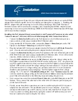
Installing the PoE Adapter Kit and connecting it to an access point:


1.


Connect the 

Data-In (LAN) 

port on the PoE Injector to a LAN (Ethernet) port on a 

router, switch, or hub using a standard RJ-45 Ethernet cable. 


2.


Using another RJ-45 Ethernet cable, connect the 

Power +


Data-Out 

port on the PoE 

Injector to the 

Power +


Data-In

 port on the PoE Splitter.  

3.


Plug the included 48V/0.4A power adapter into the PoE Injector’s 

48V/0.4A Power-In


port.  (You do not need to plug the power adapter into the wall outlet yet.)  


4.


Connect the 

Data-Out (LAN) 

port on the PoE Splitter to the LAN (Ethernet) port on the 

HWBA54G Multi-Function AP/Bridge using a standard RJ-45 Ethernet cable.  (Note: All 
access points will have a LAN port.) 


5.


Using the 

DIP switch

 that sits next to the 

DC-Out

 port on the PoE Splitter, adjust the 

voltage setting on the PoE Splitter to match that of the HWBA54G AP/Bridge (in this 
case, 12V).  (In general, for any PoE-capable network device that you connect to the PoE 
Splitter, you must adjust the Splitter’s DIP switch to match the voltage setting of the 
network device.  If you are unsure of the network device’s voltage setting, you can find it 
in the device’s user’s manual or datasheet, and sometimes on its packaging.)  The PoE 
Splitter supports three voltage settings: 5V, 7.5V, and 12V. 

The default setting is 12V

.  

Note: 

You must

 adjust the DIP switch to match the voltage setting on the network device 

before

 connecting the included power link cable (described in the following step) and 

turning the power on.   


6.


Next, connect one end of the included 

Power Link

 cable to the 

DC-Out

 port on the PoE 

Splitter.  Then, connect the other end of the cable to the HWBA54G’s power input port 
on the back of the unit.  


7.


Finally, ensure that all the connections are correct, and then plug the 48V/0.4A power 
adapter into the wall outlet.  The installation process is now complete.  If you have 
already installed and set up your access point, you can verify that the 

PoE Adapter Kit–

AP/Bridge

 system is working properly by typing the access point’s IP address into your 

web browser’s address bar and accessing the HWBA54G’s homepage. 


11 

Summary of Contents for HPOE1

Page 1: ...1 ...

Page 2: ... 15 of the FCC rules Operation is subject to the following two conditions 1 This device may not cause harmful interference and 2 This device must accept any interference received including interference that may cause undesired operation CE Mark Warning This is a Class B product In a domestic environment this product may cause radio interference in which case the user may be required to take adequa...

Page 3: ...Overview 4 Features 5 Package Content 6 Hardware Description 7 Installation 10 Technical Specifications 12 3 ...

Page 4: ...a Out port is connected to the Splitter unit s Power Data In port via a standard RJ 45 Ethernet cable As the port names indicate both data and power are transmitted via this RJ 45 cable that connects the Injector and Splitter units On the other end of the Splitter unit the LAN port is connected to a network device s LAN port via an RJ 45 cable The network device can be an access point a network ca...

Page 5: ... power and data to non PoE network devices Delivers power over up to 100 meters Short circuit protection Adjustable output settings 5v 1 5A 7 5v 1A and 12v 1A to match the power setting of your associated network device Remote power feeding Lightweight and compact Plug and Play 5 ...

Page 6: ...1 Power over Ethernet Injector 2 Power over Ethernet splitter 3 Power adapter 48V 0 4A 4 RJ 45 Ethernet Cable 5 Power Link Cable Male to Male 6 User s Manual Figure 2 Package Contents 6 ...

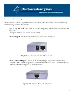
Page 7: ...the PoE Injector This port connects to a router switch or hub Power In port The Power In port supplies power into the Injector Figure 3 The Injector s Data In and Power In ports Power Data Out port This is an RJ 45 Ethernet port and connects to the PoE Splitter s Power Data In port via a standard Ethernet cable The RJ 45 Ethernet cable delivers both data and power to the PoE Splitter Figure 4 The ...

Page 8: ...et cable The RJ 45 Ethernet cable delivers both data and power to the PoE Splitter Figure 5 The Splitter s Power Data In port Data Out port This is an RJ 45 Ethernet port and connects to a network device such as an IP camera via an RJ 45 Ethernet cable This cable will transmit data to and from the network device Power Out port The Power Out port transmits DC power to a 5V 7 5V or 12V network devic...

Page 9: ...icators DIP switch The DIP switch adjusts the splitter voltage allowing for the PoE Adapter to operate with a variety of different PoE capable network devices such as IP cameras access points and more It has three voltage settings 5V 7 5V and 12V The default setting is 12V Before adjusting the DIP switch please remember to disconnect the power from the Splitter Figure 8 DIP switch 9 ...

Page 10: ...ote All network cameras whether wired or wireless will have a LAN port 5 Using the DIP switch that sits next to the DC Out port adjust the voltage setting on the PoE Splitter to match that of the HNC290G IP camera in this case 12V In general for any PoE capable network device that you connect to the PoE Splitter you must adjust the Splitter s DIP switch to match the voltage setting of the network ...

Page 11: ... the PoE Splitter you must adjust the Splitter s DIP switch to match the voltage setting of the network device If you are unsure of the network device s voltage setting you can find it in the device s user s manual or datasheet and sometimes on its packaging The PoE Splitter supports three voltage settings 5V 7 5V and 12V The default setting is 12V Note You must adjust the DIP switch to match the ...

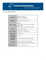
Page 12: ...ategory 3 5e 6 cable up to 100m 100Base TX UTP Category 5e 6 cable up to 100m LED System power green Power Input 100 240V 50 60Hz 0 7A Output Power 48VDC 0 4A Operating Environment 0 55 C Operating Humidity 10 90 Humidity non condensing Dimension 0 79 x 2 28 x 2 95 H x W x D 2 00cm x 5 80cm x 7 50cm H x W x D EMI Safety FCC CE C Tick VCCI 12 ...

Page 13: ... Data pin 1 2 3 6 Power out jack 5V 7 5V 12V Adjustable Maximum feeding current 1A 12V Network Cable 10Base T UTP Cat 3 4 5 cable up to 100m 100Base TX UTP Cat 5e cable up to 100m LED Power green 5V 7 5V and 12V Power Input DC 48V 0 4A Operating environment 10 90 Humidity non condensing Dimension 0 79 x 2 28 x 2 95 H x W x D 2 00cm x 5 80cm x 7 50cm H x W x D EMI Safety FCC CE C Tick VCCI 13 ...

Reviews: